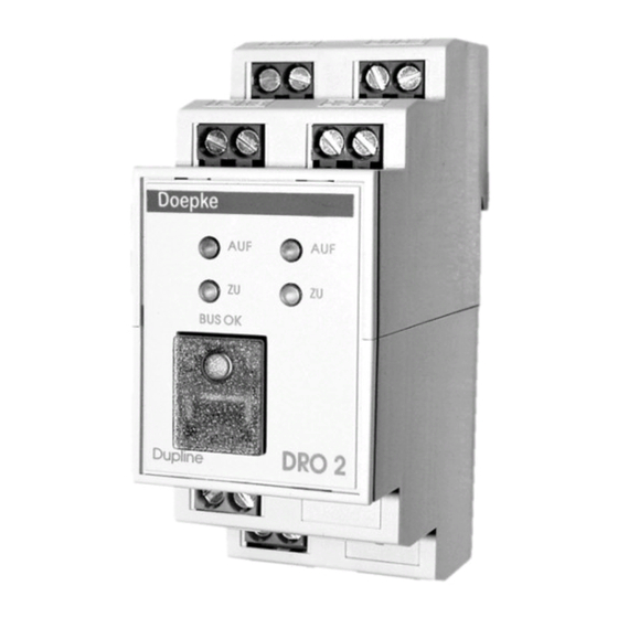
Doepke Dupline DRO 2 Manual de instrucciones - Página 6
Navegue en línea o descargue pdf Manual de instrucciones para Unidad de control Doepke Dupline DRO 2. Doepke Dupline DRO 2 8 páginas. Shutter control unit

Doepke
9. Putting into Service
Only an authorized expert is allowed to carry out the installation. When installing, the
connection diagram has to be observed. All conductors that shall be connected have to
be free of voltage. Following table shows the connections:
Terminal
1.1/1.5
Motor 1 output (UP/DOWN)
2.1/2.5
Motor 2 output (DOWN/UP)
1.3
Dupline signal conductor - (D-)
1.4
0 VDC operating voltage
Short circuits between Dupline signal conductors and the 24 V operating voltage or con-
nections to the grounding lead to malfunction and are not allowed. The correct polarity
of operating voltage and Dupline signal conductors has to be ensured.
In order to meet the requirements for protective low voltage, VDE 0100, Part 410, should
be observed and put into practice during installation.
When connecting please observe that the maximum torque of the terminals of 0.6 Nm
will not be exceeded.
The patented click-and-lock-mechanism allows an easy removal of the unit from the rail
by pushing the housing upwards until it is released.
10. Indicators
Indicator
Green "BUS OK"
LED
2 red LED „AUF"
2 red LED „AB"
11. Technical Data
Dupline
Input channels None
Output channels 4 control channels (shutters 1/2, each „Up" und
Outputs
Rated current / load capacity
6
Description
Dupline bus:
Off - bus fault / On - bus OK
All-or-nothing relay 1 / 2:
Off - no upward movement / On - upward movement
All-or-nothing relay 1 / 2:
Off - no downward movement / On - downward movement
Current input
„Down")
Type All-or-nothing relay
Voltage
Power factor
Terminal
1.2/1.6
2.2/2.6
1.7
1.8
Description
Min.
cos ϕ = 0.6 - 1
3931169/03/05/F
Description
Motor 1 phase input (L
Motor 2 phase input (L
Dupline signal conductor + (D+)
+24 VDC operating voltage
Typ.
10 µA
230 VAC
)
IN1
)
IN2
Max.
2 A
