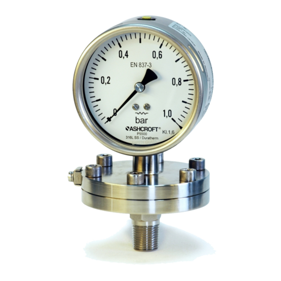
Ashcroft P6500 Manual de instrucciones de instalación y mantenimiento - Página 7
Navegue en línea o descargue pdf Manual de instrucciones de instalación y mantenimiento para Instrumentos de medida Ashcroft P6500. Ashcroft P6500 8 páginas.

7.4 Starting up
The precondition for start-up is proper installation of all electrical feed lines and metering pipes. All connecting lines
must be laid such that no mechanical forces can act on the device.
Before start-up, the seal on the pressurized connection line must be checked.
7.4.1 Zero point adjustment
The pressure gauges are supplied calibrated ex works, so that as a rule there is no need for calibration works at the
installation point.
On some devices (see order code), zero point adjustment on site is possible. For this, proceed as follows:
Depressurize the pressure metering pipe.
Open the vent valve as shown in the diagram, and carefully
remove the entire valve bushing from the housing.
Adjust the indicator arm using the zero point adjustment screw
to the zero point on the scale.
Refit the valve bushing in the housing.
Close the vent valve.
7.4.2 Setting the switch point
An adjustable lock is fitted in the front panel of the pressure gauge.
Using the removable adjustment key, the contacts mounted on the
target value indicators can be set to any point on the range covered
by the scale.
For reasons relating to accuracy of switching and the lifetime of
mechanical measurement systems, the switch points should be
positioned between 10% and 90% of the range.
Place the adjustment key on the axle of the adjustable lock.
Press the axle inwards, until the carrier arm grips behind the
adjuster pin on the target value indicator.
By turning the key, adjust the target value indicator to the
desired switch point.
Release the pressure on the axle, and remove the adjustment key.
7.4.3 Contact function
Function 1: Close contacts with the indication rising in a clockwise direction.
Function 2: Open contacts with the indication rising in a clockwise direction.
Contact assignment: 1st contact left, 2nd contact middle, 3rd contact right target value indicator
7.5 Subsequent relocation of the gauge (by the customer)
Recommendation: Do not remove the pressure gauge from one metering point and fit it in a different place,
as there is a risk of the measuring media being mixed, with unforeseeable chemical reactions.
8 Servicing
The device is maintenance-free. However, to ensure reliable operation and a long lifetime for the device, we
recommend that it is checked regularly.
8.1 Safety
When undertaking servicing work on the device, the pressure lines must be depressurized, the electrical connections
isolated from the mains supply, and the plant secured against being switched on again.
8.2 Check on function, and recalibration
The check on function and recalibration is carried out at regular intervals, depending on the application. The precise
testing cycles should be adjusted in line with the operating conditions and ambient conditions. In the event of various
device components interacting, the operating instructions for all other devices should also be taken into account.
Page 7 of 8
