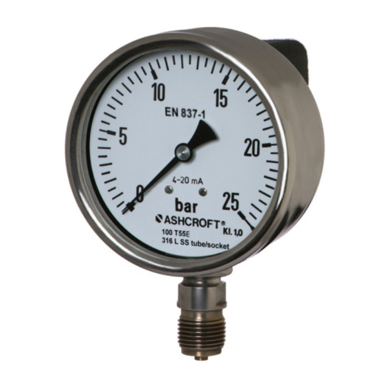
Ashcroft t5500e Manual de instrucciones de instalación y mantenimiento - Página 6
Navegue en línea o descargue pdf Manual de instrucciones de instalación y mantenimiento para Instrumentos de medida Ashcroft t5500e. Ashcroft t5500e 11 páginas. Bourdon tube pressure gauge with integrated transmitter

5 Construction and function
5.1 Overview
1
Socket and instrument connection
2
Electrical termination
3
Dial
4
Pointer
5
Cap with access to PCB
6
Vent valve
7
Case
8
Bayonet ring
5.2 Description of function
The sensing element, a bourdon tube (C-form or helical) that is welded to the socket, will be exposed from inside with
pressure. Under pressure the elastic tube is deflecting against the zero position. This deflection is proportional to the
adjacent pressure. The movement transfers the deflection to the pointer.
The display of the measured value is provided on a 270° scale (dial arc.).
The sensing element, a thin film pressure sensor that is welded to the socket, will be exposed from outside with
pressure. Under pressure the elastic diaphragm is deflecting against the zero position. This deflection is measured by
resistors of a Wheatstone bridge located at the back side of diaphragm. The PCB transfers the output signal of the
sensing element into a standard electric output signal.
5.3 Description of components
5.3.1 Scale with pointer
The pressure gauge is equipped with a dial face and pointer pursuant to EN 837-1, nominal size 100 mm.
Erläuter ung, z usätzlich ei n Hi nweis :
5.3.2 Instrument connection
The instrument connection is located on the bottom side of the pressure gauge and is a threaded pressure connection.
5.3.3 Vent valve
The vent valve for the housing is located on the top side. If the nipple is pulled out, the housing is ventilated and the
pressure which has built up in the housing due to the influence of temperature is discharged. With the valve closed,
protection class IP 65 is achieved.
5.3.4 Thin film sensing element
The pressure transmitter incorporates polysilicon thin film technology. Modern low-pressure chemical vapor deposition
methods provide simple, stable molecular bonds between the metal diaphragm and a polysilicon strain gage bridge.
There are no epoxies or bonding agents to contribute to signal instability or drift. The integral metal diaphragm and
polysilicon bridge are virtually unaffected by shock, vibration or mounting.
5.3.5 Printed circuit board
The PCB provides the signal conditioning and is equipped with pots for zero and span adjustment.
5.3.6 Electrical termination
The electrical termination is provided with standardized termination plug.
5.4 Accessories
Please contact the manufacturer regarding special tools and accessories.
Page 6 of 11
