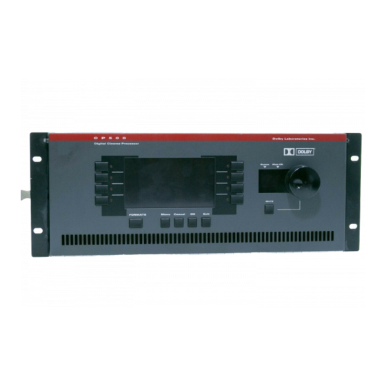
Dolby Laboratories CP500 Diagramas de referencia - Página 7
Navegue en línea o descargue pdf Diagramas de referencia para Hardware informático Dolby Laboratories CP500. Dolby Laboratories CP500 19 páginas. Digital remote controller
También para Dolby Laboratories CP500: Manual del usuario (8 páginas)

4. Bypass / Remote Connector:
Number
5. Main / LF Output Connector:
6. Crossover Output Connector
C-2
Pin
1
Bypass Power Transformer Connection, 16-18 Vac
2
Bypass Power Transformer Connection, 16-18 Vac
3
Remote Control Unit V+
4
Remote Control Unit Data
5
Remote Control Unit Ground
6
Remote Auditorium Fader +
7
Remote Auditorium Fader Ground
8
N/C
Pin
Number
1
Left Channel
2
Signal Ground
3
Right Channel
4
Signal Ground
5
Center Channel
6
Signal Ground
7
Left Surround Channel
8
Signal Ground
9
Right Surround Channel
10
Signal Ground
11
Sub Woofer Channel
12
Signal Ground
13
Hearing Impaired Channel
14
Signal Ground
15
Mono Surround Channel
(Used With Cat. No. 683 Installed):
Pin
Number
1
Left Channel HF
2
Signal Ground
3
Right Channel HF
4
Signal Ground
5
Center ChannelHF
6
Signal Ground
7
Left Surround Channel LF
8
Signal Ground
9
Right Surround Channel LF
10
Signal Ground
Signal Name
Signal Name
Signal Name
