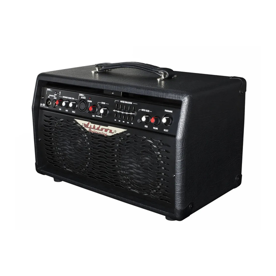
Ashdown Ashdown Acoustic Series Manual del usuario - Página 3
Navegue en línea o descargue pdf Manual del usuario para Amplificador para instrumentos musicales Ashdown Ashdown Acoustic Series. Ashdown Ashdown Acoustic Series 10 páginas.

AA-50R & AA-100R
General description
The Ashdown Acoustic 100 and 50 fulfil the requirements for a high
quality Acoustic amplification system This reissue of a timeless classic
design features a two channel preamplifier with trim controls on the in-
strument channel, Genuine Accutronics digital reverb available on either
or both channels, 5 band graphic equaliser , notch filter and aux inputs.
The addition of a blue tooth system also enables connection to a variety
of devices for music streaming for practice. A high quality Class A/B Bipo-
lar amplifier then feeds either two or four Genuine Celestion speakers.
Channel 1
Channel 1 features two inputs : one is a high impedance input (approx
4 Meg ohms) this is suitable for most non active acoustic pickups such as
Piezo etc whilst the second is a lower impedance (30K ohms) suitable for
instruments that have electronics built into them i.e. "Active".
An input level control allows the volume of this channel to be set, the sig-
nal is then sent to the Bass and Treble trim controls to enable you to tailor
the response of channel 1 to suit the instrument and your personal taste.
From here the signal is passed to the reverb circuit and then onto the
mixer section which combines the channel with channel 2
Channel 2
Channel 2 is accessed via the Balanced XLR @ 600 Ohms input on the
front panel , this input also has the benefit of Phantom power available
via the associated push switch located on the front panel.
The XLR socket also has a TRS type jack socket built into it Note a Sterio
jack plug must be used with only the tip and ring connected if you wish to
use a NON Balanced source.
AA-50R & AA-100R
USER GUIDE
Phantom power if engaged will be available on the XLR and combined
jack socket, Phantom power is typically used to power up Condenser type
microphones, it is important to ascertain whether the source you have
connected to channel 2 is designed for use with phantom power present
BEFORE turning the Phantom power on , otherwise damage to the source
may occur.
A Gain control is provided to set the appropriate level for that channel .
Mixer and distortion sensor
The mixer circuit combines channels 1 & 2 with a preset ratio therefore
the Gain controls of these channels are used to affect the mix combina-
tion you require. In the mixer section there is a distortion sensor that has
an indicator light labelled CLIP on the front panel This indicator illumi-
nates OLIVE green when the unit is switched ON and turns to BRIGHT
Green when a signal is present from either input channel. The relative lev-
els should be adjusted so that the Clip light just occasionally illuminates
RED during periods of enthusiastic playing i.e. at the loudest parts of
your performance . This will be the correct input levels to maximise signal
to noise ratio. Note the distortion sensor does NOT indicate distortion in
the power amplifier.
USER GUIDE
