DOLD MINISTART BL 9028 Traducción de las instrucciones originales - Página 4
Navegue en línea o descargue pdf Traducción de las instrucciones originales para Controlador DOLD MINISTART BL 9028. DOLD MINISTART BL 9028 6 páginas. Softstarter with braking function
Control input X1, X2
With BL 9028 softstart begins by closing switch S and braking starts when
opening switch S. When closing S during braking, softstart begins again.
A new start can only be made, after the braking cycle is completed. The
control input is triggered with rising edge.
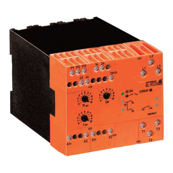
Adjustment Facilities
Potentiometer
Description
M
Starting voltage
on
t
Ramp-up time
on
I
Braking current
Br
Set-up Procedure
Softstart:
1. Start the motor via control input X1/X2 and turn potentiometer „M
up until the motor starts to turn without excessive humming.
2. Adjust potentiometer „t
" to give desired ramp time.
on
3. On correct setting the motor should accelerate up to nominal speed.
If the start takes too long fuses may blow, especially on motors with
high inertia.
- Attention: If the ramp-up time is adjusted to short, the internal
bridging contact closes before the motor is on full speed.
This leads to interruption of the softstart and to fault
message 15.
Braking:
Press stop button and adjust with potentiometer „I
the desired value. Please adjust the braking current high enough so that
the brake time is shorter than 20 sec. The brake current should be limited to
1.8 ... 2 x I
of the motor. If the brake function at 1.8 ... 2 times of rated
N
current has not finshed within 20 sec the load is too high. The next larger
motor shoud be used. To avoid an overload of the device and the motor,
the brake current should be measured with a moving coil instrument in the
motor connecting line T1.
Function test of brake circuit:
Before starting the motor the function of the braking circuit is tested by a
short braking attempt. If no current flows during the test the device goes
into failure mode. By disconnecting and reconnecting of the auxiliary
voltage the fault can be reset.
Temperature monitoring:
BL 9028 features overtemperature monitoring of its internal power semicon-
ductors. The unit is therefore protected against overheating during the set
up procedure. BL 9028 can be reset after the semiconductors have cooled
down by momentarily removing the auxiliary supply voltage.
Monitoring of the power circuit:
To protect the power circuit against overcurrent the current is monitored in
L1-T1. To high starting current, braking current or current at stalled motor
result in disconnecting the motor current and failure indication by flashing
code (see Indicators).
Safety Notes
-
Never clear a fault when the device is switched on.
-
The user must ensure that the device and the necessary
components are mounted and connected according to the locally
applicable regulations and technical standards.
-
Adjustments may only be carried out by qualified specialist staff and
the applicable safety rules must be observed.
Connection Examples
DC 24V
Initial setting
fully anti-clockwise
fully clockwise
fully anti-clockwise
"
on
" the braking current to
Br
DC 24V
4
L1
L2
L3
0V
Q1
I> I> I>
L1 L2 L3
A1(+)
T1 T2 T3
U
V
W
M
3~
L1
L2
L3
0V
Q1
I> I> I>
L1 L2 L3
A1(+)
T1
T2
T3
P1
P2
U
V
W
M
3~
T1
T2
T3
P2
U
V
W
M 3~
T1 T2 T3
P1 P2 P3
U
V
W
M 3~
S
A2
X1(+)
X2
13
BL9028.03
14
24
M10201_b
S
A2
X1(+)
X2
13
BL9028.03/010
P3
14
24
without
temperature
M12005
monitoring
P3
temperature
monitoring by
bimetallic contact
temperature
monitoring by
1...6 PTC-sensor
11.01.21 en / 335A
43
44
43
44