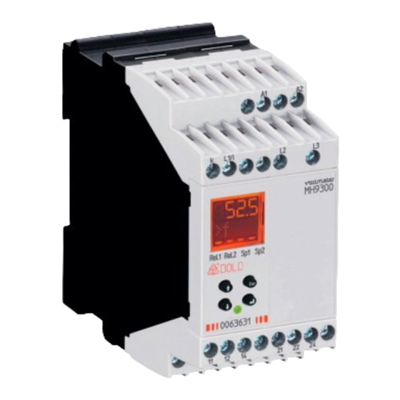
DOLD MK 9300N Técnica de control - Página 2
Navegue en línea o descargue pdf Técnica de control para Relés DOLD MK 9300N. DOLD MK 9300N 8 páginas. Multifunction measuring relay

Circuit Diagrams
A1
A2
+
L1/ i
k
L2 L3
11
12 14
11
12
14
M10139
MK 9300N.11
MH 9300.12
Connection Terminals
Terminal designation
A1 (+), A2
L1/i, L2, L3
L1/i , k
11, 12, 14
21, 22, 24
Function
After connecting the auxiliary supply to terminals A1-A2 the startup delay
disables the monitoring function so that changes on the input have no
influence on the relay output of the VARIMETER PRO. The device is in
display (RUN) mode and continuously measures the actual values. The
buttons
and
toggle between the different values. Pressing
more than 3 sec starts the input mode.
One or more measuring values can be assigned to the relay output. If the
setting value of at least one function is exceeded the relay switches and
the display indicates this state. The display is inverted, flashes and shows
measuring function and fault.
The fault memory is selectable
With button
the fault memory can be deleted.
On the unit MH9300 it is possible to assign different values to the different
relays so one can be used as pre-warning and the other as alarm output.
Relay output 1 switches when actual value exceeds the pre-warning setting
of at least one assigned measuring function.
If a second setting assigned to relay output 2 with the same measuring
function the unit gives an Alarm signal.
Remarks
To provide correct function the measuring voltage on L1/L2 has to be at
least 20 V.
Load monitoring claims a symmetric load on all 3 phases as you have it
usually with motors. The unit can also be used for single phase monitoring
by bridging terminals L2 and L3 (the display then shows U
Overload within the current range is indicated by fast flashing of the LED.
A1
A2
L1/ i
k
L2
L3
11
21
12 14
22 24
11
12
14
21
22
24
Signal designation
Auxiliary voltage AC or DC
Voltage measuring input AC
Current measuring path AC
Indicator relay (C/O contact)
Indicator relay (C/O contact)
Esc
= 0).
min
Setting
Display "Rel.2" active
Display "Rel.1" active
M10140
Selection of
Functions/Setting and
measuring values
Indication
The LED indicate the state.
green LED U
:
N
red LED (flashes)
for
orange LED:
Cursor LCD Display
2
Error memory 1 active
Error memory 2 active
Change to setup mode (3...6s)
Change to Run mode (3...6s)
LED status indication
M10933_a
on, when auxiliary voltage present
at overload at current path
No measurement, unit in input mode
Active manual reset
Manual reset activated: flashes when me-
mory mode is ON and relay in failure state.
Reset with button "
"
Contact state of the output relays
11.01.16 en / 627
