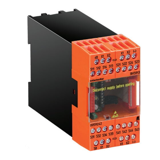
DOLD SAFEMASTER M BG 5913.08/ 0 Series Técnica de seguridad - Página 2
Navegue en línea o descargue pdf Técnica de seguridad para Sistemas de E/S DOLD SAFEMASTER M BG 5913.08/ 0 Series. DOLD SAFEMASTER M BG 5913.08/ 0 Series 12 páginas.

Circuit diagrams
48
X1
X2
S11
S12
S13
S14
S21
A1+
48
S11
S12
S13
S14
S21
S22
S23
S24
S31
(-)
X1 X2 X1 X2 X1 X2 X1 X2 (-)
A1+
58
S31
S32
S33
S34
S41
58
X1
X2
BH 5913
General information SaFeMaSTer
The maximum configuration of the SAFEmASTER
system is as follows:
• the control unit BH 5911
• up to 3 input modules BG 5913, or BG/BH 5914, BG/BH 5915
• up to 3 output modules BG 5912
• 1 diagnostic module BG 5551 for CANopen, or
• 1 diagnostic module BG 5552 for Profibus-DP
The BH 5911 controls the whole system.
The input/output modules can be used to expand the control unit in a
modular way into a multi-functional safety system.
To transmit status messages of the individual modules to a moni to ring or
control unit, one of the following diagnostic modules may be connected:
• BG 5551 for CANopen
• BH 5552 for Profibus-DP
Notes
In respect of function and settings, the modules BG 5913 and
BH 5913 are completely identical.
• The modules BG 5913 have 8 inputs with one common ground. This is
the ground of the overall system. They are suitable for all applications in
which volt free contacts are used, or where there is a common ground
(e.g. 2-channel light curtains). They need only 8 terminals and thus only
have an overall width of 22.5 mm.
• The modules BH 5913 have 8 completely DC-decoupled inputs. This
allows with setting 1 and 3 (4 lightcurtains) to connect also 4 two-channel
e-stop buttons with long connection wires with static signal potental. Here,
short-circuit monitoring is effected by a certain type of wiring according
to the application examples.
Indication
Green LEDs:
on, when all inputs are present and start
button activated.
White LEDs Run1/
Run 2 and outputs
48 and 58:
indicate the current status of the module.
(-)
X1
X2
S22
S23
S24
S32
S33
S34
S41
S42
S43
S44
S42
S43
S44
M8742
(-)
X1
X2
M
®
m multi-function safety
®
Setting of the Module
The module is assigned to the start inputs and the safety outputs via the
DIP switches.
The combinations of individual functions are set via the rotary switches.
To prevent accidently adjustments, these elements are covered by a front
plate and are redundant.
green LED "en 1"
0
2
3
start
output
4
input
Mod3
T1
1
1
S1
S2
9
7
8
Mod2
T2
2
2
white LED
Mod1
T3
3
3
"run 1"
Base
T4
4
4
white LED
Mod3
T1
5
5
"run 2"
Mod2
T2
6
6
0 1 2
Mod1
T3
7
7
Base
T4
8
8
5
6
9
7
M8941_b
green LED "en 2"
on
off
Note:
• Settings to the unit must be performed by skilled personnel while
the unit is disconnected.
• Before the front cover is removed, antistatic precautions must be
observed.
Setting of the Modules
Sw.
Function
0
4 Emergency stop 2-channel, autostart
1
4 light curtains category 4, autostart
2
4 Emergency stop 2-channel, manual start
3
4 light curtains category 4, manual start
4
4 safety gates with 2 single contacts
5
2 safety gates with 2 changeover contacts
1 safety gate with 2 twin contacts and 1 single contact,
6
manual start (plastic injection moulding machines) to EN 201
1 safety gate with 3 twin contacts, manual start
7
(plastic injection moulding machines) to EN 201
8
4* two-hand control IIIA acc. to EN 574
9
2* two-hand control IIIC acc. to EN 574
When using setting 8 or 9 the user has to indicate clearly on the device
which type of 2-hand function is adjusted (IIIa or IIIC).
2
plate
BG 5913.08/_0_ _ _ / 11.05.09 e
