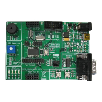
Cypress F2MC-8FX Series Nota de aplicación - Página 4
Navegue en línea o descargue pdf Nota de aplicación para Placa base Cypress F2MC-8FX Series. Cypress F2MC-8FX Series 16 páginas. How to make on-board debug
También para Cypress F2MC-8FX Series: Cómo hacerlo (14 páginas)

2.3
Registers
Please refer to Chapter 11 and Chapter 22 of MB95200H/210H Series Hardware Manual for detailed register setting.
2 . 3 . 1
W a t c h d o g T i m e r C o n t r o l R e g i s t e r ( W D T C )
This register is used to activate or clear the watchdog timer.
Address
bit7
000C
CS1
H
software
R/W
hardware
R0/WX
2 . 3 . 2
W a t c h d o g T i m e r S e l e c t i o n I D R e g i s t e r ( W D T H , W D T L )
The two registers are used to select hardware or software watchdog timer.
Address
bit7
0FEB
H
WDTH
WDTH7
0FEC
H
WDTL
WDTL7
R/WX
R/W
: Readable/writeable (Read value is the same as write value)
R/WX
: Read only (Readable, writing has no effect on operation)
R0/WX : Undefined bit (Read value is "0", writing has no effect on operation)
R1/WX : Undefined bit (Read value is "1", writing has no effect on operation)
: Write only (Writable, "0" is read)
R0/W
www.cypress.com
Figure 2. WDTC
bit6
bit5
bit4
CS0
CSP
HWWDT
R/W
R/W
R0,WX
R0/WX
R1/WX
R1,WX
Figure 3. Watchdog Timer Selection ID Register (WDTH, WDTL)
bit6
bit5
WDTH6
WDTH5
WDTH4
WDTL6
WDTL5
WDTL4
R/WX
R/WX
R/WX
Document No. 002-05336 Rev.*A
F²MC-8FX Family, MB95200H/210H Series Watchdog Timer
bit3
bit2
WTE3
WTE2
R0/W
R0/W
R0/W
R0/W
bit4
bit3
bit2
WDTH 3
WDTH 2
WDTL 3
WDTL 2
R/WX
R/WX
bit1
bit0
Initial value
WTE1
WTE0
R0/W
R0/W
00000000
R0/W
R0/W
00110000
bit1
bit0
WDTH 1
WDTH 0
WDTL 1
WDTL 0
R/WX
R/WX
B
B
Initial value
xxxxxxxx
xxxxxxxx
3
