AERMEC PTI Manual - Página 2
Navegue en línea o descargue pdf Manual para Control Panel AERMEC PTI. AERMEC PTI 16 páginas. Control panel with electronic thermostat for fan coils fcx series

FUNZIONAMENTO PTI • PTI OPERATION
FONCTIONNEMENT DU PTI • FUNKTIONSWEISE PTI
Il pannello comandi è alloggiato sotto lo sportellino con gri-
glia a destra o a sinistra del ventilconvettore (fig. 4).
Il pannello può essere protetto da manomissioni, bloccando
con una vite lo sportellino di copertura.
Il termostato di regolazione controlla il funzionamento del
ventilconvettore per mantenere nell'ambiente la temperatura
impostata.
Il modo di funzionamento in riscaldamento o in raffreddamen-
to, avviene in modo automatico (cambio stagione) e dipende
dalla temperatura dell'acqua circolante nell'impianto.
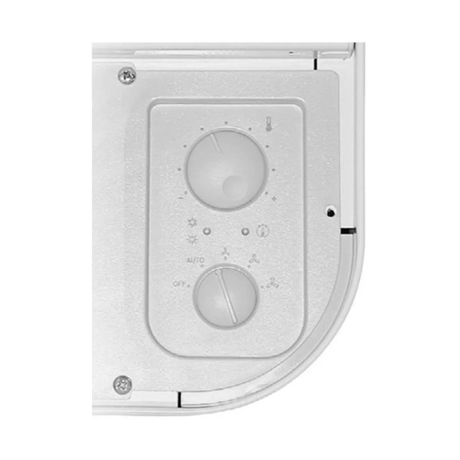
Il pannello comprende (fig. 1):
–(A)
selettore acceso-spento e modo di ventilazione;
–(B)
selettore della temperatura;
–(C)
led indicatore del modo di funzionamento (blu,
rosso e fucsia);
–(D)
led giallo indicatore di richiesta ventilazione
(o anomalie di funzionamento se lampeggiante).
Le panneau de commande se trouve sous le volet à grille, à
droite ou à gauche du ventilo-convecteur (fig. 4).
Le panneau peut être protégé contre les manipulations en
bloquant le volet de couverture à l'aide d'une vis.
Le thermostat de régulation contrôle le fonctionnement du
ventilo-convecteur, de façon à maintenir constante la
température programmée dans la pièce.
Le mode de fonctionnement Chauffage ou Rafraîchissement
se fait automatiquement (changement de saison) et il
dépend de la température de l'eau qui circule dans l'instal-
lation.
Le panneau comprend (fig. 1):
-(A)
sélecteur marche-arrêt et mode de ventilation;
-(B)
sélecteur de la température;
-(C)
led indiquant le mode de fonctionnement (bleu,
rouge et fuchsia);
-(D)
led jaune indiquant une demande de ventilation
(ou des anomalies de fonctionnement si elle clignote).
Fig.1
B
-
+
C
A
The control panel is located under the door with grid on the
left or right-hand side of the fancoil (fig. 4).
To prevent tampering with unit controls, secure the door
with a screw.
The thermostat controls the operation of the fancoil, which
is regulated to maintain the temperature setting.
The unit operating mode switches automatically between
heating and cooling (season change), depending on the
temperature of the water in the system.
The panel features (fig. 1):
-(A)
ON/OFF and ventilation mode selector switch;
-(B)
temperature selector switch;
-(C)
operating mode LED indicator lamp (blue, red and
pink);
-(D)
ventilation request yellow LED lamp (also indicates
operating fault when flashing).
Das Bedienteil ist unter der Klappe mit Ausströmgitter rechts
oder links am Gebläsekonvektor angeordnet (Abb. 4).
Es kann durch Sichern der Klappe mit einer Schraube gegen
unbefugtes Verstellen geschützt werden.
Der Temperaturregler steuert den Betrieb des
Gebläsekonvektors so, dass die eingestellte Raumtemperatur
konstant gehalten wird.
Die Einschaltung der Betriebsart Heizen oder Kühlen erfolgt
automatisch (Umschaltung von Heizen/Kühlen) in Funktion
der Temperatur des in der Anlage zirkulierenden Wassers.
Auf dem Bedienteil sind folgende Elemente angeordnet
(Abb. 1):
-(A)
Wahlschalter Ein/Aus und Gebläsebetrieb;
-(B)
Temperaturschalter;
-(C)
Anzeige-Led der Betriebsart (blau, rot und
fuchsia);
-(D)
Gelbe Led zur Anzeige der Anforderung des
Gebläsebetriebs (oder Betriebsstörungen bei Blinken).
V1 =Velocità minima
D
V2 =Velocità media
V3 =Velocità massima
Minimun fan speed
Vitesse minimale
Mindestgeschwindigkeit
Mediun fan speed
Vitesse moyenne
Mittlere Geschwindigkeit
Maximun fan speed
Vitesse maximale
Höchstgeschwindigkeit
3
