ACR Electronics NAUTICAST 2645 Apéndice del Manual de asistencia de productos - Página 12
Navegue en línea o descargue pdf Apéndice del Manual de asistencia de productos para GPS ACR Electronics NAUTICAST 2645. ACR Electronics NAUTICAST 2645 15 páginas. Portable ais (solas and inland ais) automatic identification system

5.9 Antennas
5.9.1 External VHF-Antenna
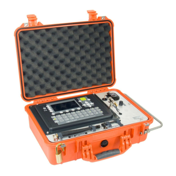
Always connect your VHF rubber duck antenna to the connector labeled VHF.
If another external VHF antenna is used, connect it to the same port. You will need to ensure your antenna
connection is converted to TNC Male to mate to the VHF antenna port. Ensure antenna is connected
before powering unit on.
5.9.2 Internal GPS antenna vs. external GPS antenna
The internal GPS antenna is connected by default. If an external GPS antenna is needed then the internal
connection needs to be disconnected. This connector is labeled and readily available when you open
the case. Open box and disconnect internal GPS connector from GPS connection tee.
5.9.3 Entering ship's data
Set up your Portable AIS as described in the Operation section. The transponder is now ready to be
programmed with ship's data. Place the switch in the ON position. To start the AIS see chapter 6.
Operation.
You must open the case and enter your MMSI and user information before the unit will transmit AIS
messages. Enter data through the internal keyboard and display system. Please refer to the SOLAS AIS
User Manual or Inland AIS User Manual for more information on this topic. Ensure all antennas and
connectors are attached.
CAUTION: Be sure to keep track of user passwords!
6
Operation
6.1 Readying for operation
Open the case and remove the VHF and Wi-Fi™ antennas. Install these antennas in the appropriate
connections on the side of the case.
EXTERNAL DC OPERATION (18-36Volts):
To operate the transponder from ship's power or any external DC power source, attached DC power cable
to the unit's power connector and attach leads of cable to a DC power source. Move the power supply
switch to the Ext DC Power position. Push the START SWITCH (momentary toggle switch) to the right for
powering on the unit. The red LED indicates the unit has powered on is ready for operation. The External
DC Operating Range is 18-36 Volts.
INTERNAL BATTERY OPERATION:
To operate transponder on the internal rechargeable battery, move the power supply switch to the Battery
Power position. Push the momentary toggle switch to the right for starting the AIS operation (hold for 1
second). The red LED indicates the unit is powered on. The yellow LED would indicate an empty battery
and switch off the AIS and recharge battery. You can see the yellow LED when you hold the momentary
toggle switch in position START.
NOTE: When red LED is active (steady state), the power is ON.
The yellow LED indicates a low battery. AIS is switched OFF automatically.
Portable AIS Manual Addendum
12
Y1-03-0243D
