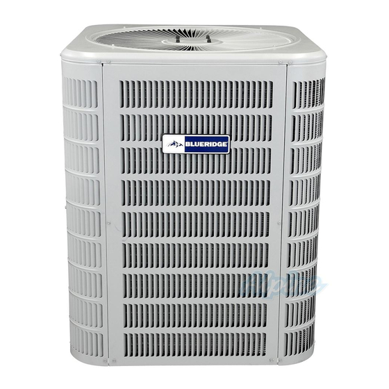
Blueridge BA13 Manual de instrucciones de instalación - Página 3
Navegue en línea o descargue pdf Manual de instrucciones de instalación para Aire acondicionado Blueridge BA13. Blueridge BA13 19 páginas. Single stage
También para Blueridge BA13: Manual de instrucciones de instalación (9 páginas)

Elevate Unit
Accumulation of water and ice in base pan may cause
equipment damage.
Elevate unit per local climate and code requirements to
provide clearance above estimated snowfall level and
ensure adequate drainage of unit. Use snow stand in areas
where prolonged freezing temperatures are encountered.
If conditions or local codes require the unit be attached to
pad or mounting frame, tie down bolts should be used and
fastened through knockouts provided in unit base pan.
Clearance Requirements
When installing, allow sufficient space for airflow clearance,
wiring, refrigerant piping, and service. For proper airflow,
quiet operation and maximum efficiency. Position so water,
snow, or ice from roof or eaves cannot fall directly on unit.
Refer to Table 2 for installation clearances.
Location
Sides
Top**
Between units
* Must be one of the sides adjacent to the control box.
** Maximum soffit overhand is 36".
Table 2. Clearances
6"*
NOTE: See Table 2 for specific minimum clearance guidelines.
Figure 2.
508255-01
CAUTION
Clearance
1st side*
30"
2nd side
36"
3rd side
12"
4th side
6"
48"
24"
24"
30" around
Control
Box
DO LOCATE THE UNIT:
•
With proper clearances on sides and top of unit
•
On a solid, level foundation or pad (unit must be level
to within ± 1/4 in./ft. per compressor manufacturer
specifications)
•
To minimize refrigerant line lengths
DO NOT LOCATE THE UNIT:
•
On brick, concrete blocks or unstable surfaces
•
Near clothes dryer exhaust vents where debris
accumulates
•
Near sleeping area or near windows
•
Under eaves where water, snow or ice can fall directly
on the unit
•
With clearance less than 2 ft. from a second unit
•
With clearance less than 4 ft. on top of unit
Rooftop Installations
Install unit at a minimum of 6" above surface of the roof
to avoid ice buildup around the unit. Locate the unit
above a load bearing wall or area of the roof that can
adequately support the unit. Consult local codes for rooftop
applications.
If unit cannot be mounted away from prevailing winds, a
wind barrier should be constructed. Due to variation in
installation applications, size and locate barrier according
to the best judgment of the installer.
Refrigeration Piping
•
Use only refrigerant grade copper tubes.
•
Split systems may be installed with up to 50 feet of
line set (no more than 20 feet vertical) without special
consideration (see long line set guidelines).
•
Ensure that vapor and liquid tube diameters are
appropriate to capacity of unit.
•
Run refrigerant tubes as directly as possible by
avoiding unnecessary turns and bends.
•
When passing refrigerant tubes through the wall, seal
opening with RTV or other silicon-based caulk.
•
Avoid direct tubing contact with water pipes, duct work,
floor joists, wall studs, floors, walls, and any structure.
•
Do not suspend refrigerant tubing from joists and
studs with a rigid wire or strap that comes in direct
contact with tubing.
•
Ensure that tubing insulation is pliable and completely
surrounds vapor tube.
It is important that no tubing be cut or seals broken until you
are ready to actually make connections to the evaporator
and to the condenser section. DO NOT remove rubber
plugs or copper caps from the tube ends until ready to
Issue 2212
Page 3 of 19
