Ambu aScope Manuel d'utilisation - Page 11
Parcourez en ligne ou téléchargez le pdf Manuel d'utilisation pour {nom_de_la_catégorie} Ambu aScope. Ambu aScope 17 pages.

-
Luer channel
9
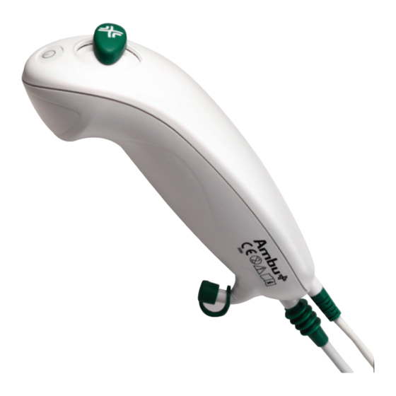
On/off button
10
Bending control lever
-
Protection pipe
-
Packaging
Table 4 – Functions and materials
8.2 Ambu® aScope™ Monitor
The monitor displays the video image from the Ambu® aScope™. On startup, it powers the Ambu® aScope™, configures it and checks information from
the Ambu® aScope™ to ensure the Ambu® aScope™ usage is acceptable.
1
2
7
8
6
5
Figure 2 - The Ambu® aScope™ Monitor
Number
Part
1
Monitor frame
2
Monitor screen
3
Bracket
4
Power supply
5
On/off button
6
Connection for
for the Ambu® aScope™
7
Brightness
8
Contrast
9
Power
10
Video out
Can be used only for topical anaesthesia.
Turns the Ambu® aScope™ on and off
Moves the distal tip up or down
Protects the insertion cord during
transport and storage
Sterile barrier
3
4
Function
-
Shows the picture from the camera
Secures the monitor to e.g. an IV pole
Powers the system
Push button for power ON before
intubation and power OFF after
intubation.
Power supply and data connection
This button controls and
adjusts the brightness.
This button controls and
adjusts the contrast.
Power inlet for charging the monitor
The monitor provides a buffered video
output of the video input from the
Ambu® aScope™. This output is
electrically isolated from the medical
device by the monitor. The signal is a
composite video NTSC signal
PU (Polyurethane)
PET (Poly Ethylene Phthalate)
MABS (Methyl Acrylonitrile
Butadiene Styrene)
PP (Polypropylene)
Cardboard, tyvek
13
12
11
Material
PC (Polycarbonate) /
ABS (Acrylonitrile Butadiene)
Glass
POM -GF25 (Polyoxymethylene
with 25% glass filler) + aluminium
PC (Polycarbonate)
PC (Polycarbonate)
PC (Polycarbonate)
/ABS (Acrylonitrile Butadiene)
Silicone
Silicone
-
-
9
10
11
