AMC CVT3100MKII Instructions pour l'installation et le manuel d'utilisation - Page 7
Parcourez en ligne ou téléchargez le pdf Instructions pour l'installation et le manuel d'utilisation pour {nom_de_la_catégorie} AMC CVT3100MKII. AMC CVT3100MKII 13 pages. Integrated valve amplifier

OPTION: COAXIAL INPUT
AMC 24bit/192KHz S/PDIF DAC Module,
MD1108s, can replace PHONO module to
have digital input in CVT3100mKII.
LOUDSPEAKER CONNECTIONS
The loudspeaker output terminals will
accept
4mm(banana)plugs,
connectors, pin connectors or bare wires.
The amplifier has speaker outputs that
will match 4 - 8 ohm speakers. Confirm
the impedance of your speakers then
connect as follows:
For 8 ohm speakers, connect the
negative (black) speaker wire to the
"common" negative binding post. Then
connect the positive (red) cable to the 8
ohm red binding post.
For 4 ohm speakers, the negative (black)
connections are the same as the 8 ohm,
but the positive or red connection must be
to the 4 ohm binding post.
Your AMC amplifier is capable of
generating high peak currents, so all
connections must be checked to avoid
inadvertent short circuits, and to ensure a
good clean contact.
UNDER NO CIRCUMSTANCES SHOULD
THE OUTPUTS BE SHORTED TOGETHER.
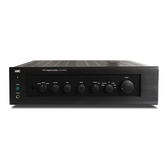
FRONT PANEL CONTROLS
POWER SWITCH
The amplifier is turned on by depressing
the power switch. The small indicator
above the switch will glow blue. Before
switching on, always set the volume
control to minimum to avoid damage to
your loudspeakers.
spade
Note:
Your AMC amplifier will play music
almost immediately after being switched
on. However, in common with other
audiophile products, the internal circuits
take some time to stablize fully, and the
best possible sound quality may not be
obtained until the amplifier has had some
time(possibly an hour or two) to warm up.
INPUT SELECTION
The rotary input selector switch selects
which input signal (Phono, iPod/DAC,
CD, Tuner, Video or Aux) is fed to the
power amplifier. The selected signal is
also fed to the "Tape out" sockets for
recording.
TAPE MONITOR SWITCH
The Tape Monitor switch is generally left
in the "Source" position, so that the
program selected by the input switch is
routed to the loudspeakers/headphones.
If the Tape Monitor switch is turned to the
"Tape" position, the signal from the tape
r
ecorder is routed to the loudspeakers/
headphones.
If your tape machine is a three head type
suitable for A/B monitoring, then turning
the Tape Monitor switch to the "Tape"
position will allow full off-tape monitoring
of the recorded signal to be carried out
via the loudspeakers/headphones.
VOLUME CONTROL
The volume control adjusts the overall
loudness level of the sound. It has no
effect on the level of the signals fed to the
TAPE OUT jacks for tape recording. The
Volume control is designed for accurate
6
