AMC iA4X125 Manuel de l'utilisateur - Page 7
Parcourez en ligne ou téléchargez le pdf Manuel de l'utilisateur pour {nom_de_la_catégorie} AMC iA4X125. AMC iA4X125 12 pages. Installation amplifier
Également pour AMC iA4X125 : Manuel de l'utilisateur (7 pages)

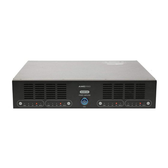
Functions description
SIGNAL INDICATOR
Signal LED indicates audio signal in the amplifiers input.
OUTPUT CONFIGURATION INDICATOR
Amplifier output can be configured for 4Ω, 70V and 100V audio system by using switch in the rear panel.
Output configuration LED indicates what kind of sound system is selected. Configuration depends on the
connected speaker type. Output configuration switch must be set to position "4Ω" when low impedance
loudspeaker (8 Ω or 4Ω) is connected, position "70V" or "100V" suitable for loudspeaker with impedance
matching transformer inside.
PROTECT INDICATOR
After power on protection LED starts illuminate and goes off after few seconds if the amplifier is not
damaged. It is normal if protection indicator illuminates and then slowly fades after amplifier off.
VENTILATION HOLES
Cool air is pulled in through the front panel fan filters and eliminated through the rear panel ventilation
holes.
POWER SWITCH
Use this switch to power on or off amplifier.
BALANCED XLR INPUT
This is balanced XRL line level audio input. Gain of this input can be adjusted by using gain control knob
located above input connectors.
INPUT GAIN CONTROL
This control allows you to precisely adjust audio level in the input. Turn knob clockwise to increase and
counterclockwise to decrease input gain. Input level can be adjusted from -∞ to 0 dB.
OUTPUT CONFIGURATION SWITCH
Amplifier output can be configured for 4 Ω, 70V and 100V audio system by using output configuration
switch. Configuration depends on the connected speaker type. Output configuration switch must be set
to position "4 Ω" when low impedance loudspeaker (8 Ω or 4Ω) is connected, position "70V" or "100V"
suitable for loudspeaker with impedance matching transformer inside.
INPUT MODE SELECTOR
There are available two input modes, single and dual.
Dual mode: This is general used mode; each input is directed to this own output. All inputs require audio
signal and all amplifier outputs work independently.
Single mode: This mode allows two channels operate in parallel with same signal. In this mode two channel
inputs are internally connected. Only one input require audio signal in order to active two amplifiers outputs.
Do not use single mode then feeding the amplifier with two separate signals.
FILTER SWITCH
Filter reduce low and high audio frequency at 200 Hz and 10 kHz points by -3dB.
AMPLIFIERS OUTPUT
Use this connector to connect amplifier to the loudspeakers. Please take attention to the loudspeakers
impedance and select corresponding output configuration by using output configuration switch. Please
note: incorrect output configuration can damage loudspeaker or amplifier!
MAIN POWER CONNECTOR
This connector is designed for connecting main power to the amplifier. Connector is combined with fuse
holder.
