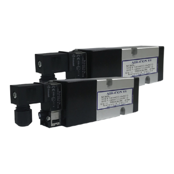
Flo-Tite SV Series Manuel d'installation, d'utilisation et d'entretien - Page 2
Parcourez en ligne ou téléchargez le pdf Manuel d'installation, d'utilisation et d'entretien pour {nom_de_la_catégorie} Flo-Tite SV Series. Flo-Tite SV Series 5 pages. Solenoid valves

Those solenoid spool valves are designed to operate with filtered (<=40µm), dry or lubricated air or neutral
gas and within the technical characteristics specified on the nameplate and the Data Sheet.
PNEUMATIC CONNECTION:
General Recommendations
Connect pipers for the required functions in accordance with this documentation and the port markings on
the product. Make sure that no foreign matter enters the system. Correctly support and align pipes to prevent
mechanical strain on the valve.
When tightening, do no use the valve as a lever. Locate wrenches as close as possible to connection point. To
avoid damage to the equipment,
Connection of the Spool Valve
SV Series serves exclusively as a 3/2, 5/2 or 5/3 solenoid valve. Pressure inlet at port 1 on the body of
The
the valve. Pressure outlet at port 2 and 4 on the body or on the interface plates. Exhaust at ports 3 and 5 on
the body of the valve. For technical details, please consult the factory or a Flo-Tite representative.
Connection of Pilot Exhaust
The standard model has a 03 exhaust port at the end of the pilot valve. Just attach and tighten a M8x0.75
female nut supplied on it.
MANUAL OVERRIDE OPERATION:
For S4/S4-2
Press the button of override, turn left, switch the override
into horizontal position with the body into manual status.
Vertical in Auto status,
horizontal in Manual status
This means the solenoid
valve is in Manual Status
ELECTRICAL CONNECTION:
General Recommendation
• Electrical connection must be made by qualified personnel and according to
applicable local standards and regulations.
• Before any electrical connection, turn off the electrical current to power off the
components.
• Depending on the voltage, electrical components must be grounded according
to local standards and regulations.
• Most valves are designed to continuous duty, To prevent the risk of personal
injury, do not touch operating condition.
• Standard coils (C0)
Electrical connection is made with detachable plug connector for cable dia.
6-8mm (see fig.), rotatable by 180 increments (3 pins: 1, 2 electric pins+PE)
DO NOT OVER TIGHTEN
This means the solenoid
valve is in Auto Status
22-22 IOM-SV /SV-2022
pipe connections.
For S4
1 stands for Manual, 0 stands for Auto-Switch.
To override , turn clockwise to turn the solenoid
valve from Auto status to Manual status.
This means the solenoid
valve is in Manual Status
Page 2
This means the solenoid
valve is in Auto Status
