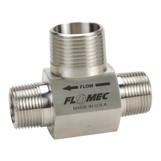
Flomec G Series Manuel du propriétaire du produit - Page 5
Parcourez en ligne ou téléchargez le pdf Manuel du propriétaire du produit pour {nom_de_la_catégorie} Flomec G Series. Flomec G Series 20 pages. Industrial and chemical models
Également pour Flomec G Series : Manuel du propriétaire (16 pages), Manuel du propriétaire du produit (20 pages)

When there is entrained air in the process line, an air eliminator should be used.
This entrained air causes air pockets and these air pockets will cause the rotor to
spin at a faster rate than liquid, thus resulting in in- correct readings, which results
in an overstatement of actual flowrate and volume. This condition can damage the
flowmeter.
In process lines where particulates are present, a filter/strainer should be used.
Refer to the table below for the recommended mesh size.
Turbine
Flowmeter Size
½ inch
¾ inch
1 inch
1-½ inch
2 inch
Disassembling the Turbine
1. Disconnect the turbine flowmeter cable from the magnetic pickup. (Refer to
Figure 1.)
2. Remove the magnetic pickup.
3. Ensure that the process line is depressurized and empty prior to removal of the
turbine flowmeter. Remove the turbine flowmeter from the process line.
4. Using a small screwdriver or similar tool, insert it into the radius notch of the
retaining ring, pull away from the groove and up, removing the retaining ring
from one end of the turbine flowmeter. This will allow the support to slide out
of the turbine flowmeter body. Remove the rotor before proceeding to the other
support.
NOTE: To remove the other support, simply repeat this operation.
5. Once the turbine flowmeter is taken apart, inspect the turbine flowmeter body
for signs of wear or defects. The body bore should be smooth and show no
evidence of wear.
NOTE: Do not install a new replacement kit into a turbine flowmeter body that
shows significant signs of wear.
6. Examine the rotor for broken and/or bent blades.
7. Examine the supports for signs of deterioration, such as wear marks and/or
burrs along the outer edge of the support vanes.
8. When the rotor or the supports show any sign of deterioration, a new
replacement kit should be installed. Do not install a new replacement kit into a
defective turbine flowmeter body.
Mesh Size
40
40
40
18
14
MAINTENANCE
5
WARNING
