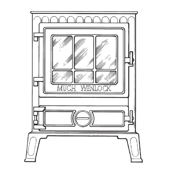
Coalbrookdale MUCH WENLOCK Manuel d'instructions d'installation - Page 4
Parcourez en ligne ou téléchargez le pdf Manuel d'instructions d'installation pour {nom_de_la_catégorie} Coalbrookdale MUCH WENLOCK. Coalbrookdale MUCH WENLOCK 8 pages. Freestanding much wenlock stove with boiler
Également pour Coalbrookdale MUCH WENLOCK : Mode d'emploi (5 pages), Manuel d'utilisation (8 pages)

the fan or overhead cooker hood, then add this
compensatory area to that recommended for the
appliances primary air needs, to form a permanent air
vent.
3. Ensure the wall location of the fan does not deprive
the appliance of primary air.
FLUE LAYOUT
In Fig. 1b and 2a the stove is installed in an existing
recess directly below the chimney flue. The exit end of
the flue pipe must extend a minimum of 150mm into the
overhanging brickwork. Any cavities or pockets above the
register plate should as far as possible be filled with the
flue pipe exit extended into the throat of the chimney.
If a flue liner or insulated chimney is used, the diameter
should not be less than 175mm and 150mm respectively.
Fig. 2b shows a back flue outlet into a chimney brickwork.
In Fig. 3 the stove is connected to an existing brick flue
with a length of flue pipe. Square bends and horizontal
runs must not be used and a cleaning door included at
every bend.
EXTENDED LENGTHS OF HORIZONTAL PIPEWORK
MUST BE AVOIDED AND ARE NOT RECOMMENDED,
AND SHALL NOT EXCEED 150mm.
NOTE: WHATEVER METHOD OF INSTALLATION IS
UTILISED, AIR MUST NOT BE ALLOWED TO ENTER
THE CHIMNEY EXCEPT THROUGH THE STOVE AND
ALL JOINTS MUST BE AIR-TIGHT. IF THE CHIMNEY IS
UNLINED AND THERE IS ANY DOUBT ABOUT ITS
CONDITION, IT SHOULD BE LINED IN ACCORDANCE
WITH CURRENT BUILDING REGULATIONS.
PROVISION MUST ALWAYS BE MADE FOR SWEEPING
THE CHIMNEY.
IMPORTANT: CEMENT PIPES AND FITTINGS MUST
NOT BE USED WITHIN 2m OF THE STOVE OUTLET
CHIMNEYS OF PLAIN PIPE ARE NOT RECOMMENDED
BUT CERTAIN PROPRIETARY MAKES OF INSULATED
CHIMNEY ARE SUITABLE.
INSTALLATION
Handle the firedoor with care to ensure the glass panel
remains intact.
The stove is delivered fully assembled but all fire cement
joints should be examined for soundness and if
necessary, re-sealed before installation.
After unpacking the stove, remove all packaged parts
from inside the stove and inspect the stove to ensure no
damage gas occurred during delivery.
If there is a problem, contact your local stockist.
Packaged parts contain a Flue Outlet Blanking Plate, Flue
Collar (for top or back outlet) and Operating Tool Support
Collar Cradle complete with two screws to secure the
Cradle to the bottom R.H. side of stove.
1. Plug any of the 1in. BSP boiler connections not
required and fit half unions as required.
2. Position the stove in required position relative to
chimney flue and on non-combustible hearth ensuring
there is sufficient room allowed on stove R.H. side to
enable operation of riddling tool.
Blank off and seal with cover plate, flue outlet not
used.
3. Cut length of 150mm diameter pipe to suit chosen
method of flue connection. Insert flue pipe spigot in
stove outlet socket and caulk joint with soft rope and
cement.
Top Flue Outlet installations must incorporate an
access door in the flue pipe near the surface of the
stove for flue cleaning.
4. Connect flue pipe to chimney with selected method.
5. Making connections to the boiler with provision for
draining at the lowest point, fill with water and test.
Make good any brickwork around the pipes.
6. Check that the bottomgrate reciprocates correctly and
that the front firebar is correctly located.
COMMISSIONING
Check that the system is full of water and free from air
locks.
a. When lighting, open firedoor and place paper and
sticks with a small quantity of fuel onto the
bottomgrate, ignite paper and set the ashpit door
spinwheel fully open and lock firedoor.
When established, balance the water system.
b. With the appliance under fire, check for soundness of
seals/joints and that the flue functions correctly in
permitting all smoke and fumes to be vented through
the chimney.
4
