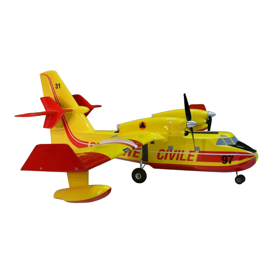
aero-naut Canadair CL-415 Instructions de construction - Page 13
Parcourez en ligne ou téléchargez le pdf Instructions de construction pour {nom_de_la_catégorie} aero-naut Canadair CL-415. aero-naut Canadair CL-415 13 pages.

30
M2 screw and nut
31
Solder washer (wheel retainer)
32
Axis of finlets offset approx. 2° right
33
Tailplane structure before elevators are separated
34
Aluminium strap, 10 x 1 x 130 mm
35
Section B-B
36
Edge of decal
37
Glue receiver aerial guide sleeve (20) to the fuselage side
38
Centre of Gravity (C.G.) 70 - 85 mm
39
Fix receiver to fuselage side with Velcro tape
40
Longitudinal dihedral: wing incidence +0.5° to +0.75° relative to tailplane
41
Flight battery: 10 - 12 cells
42
View B
43
View A
44
View F
45
Align parts (13) and (14) in the T-piece (15), solder joint
46
Cut 3 mm slot
47
Scale elevator outline
48
We reserve the right to modify any feature in order to improve our products
49
Opening for motor power cables
50
Opening for two servo leads
51
Right-hand wing panel shown with all sheet panels omitted
52
Motor power cables
53
Servo lead
54
Landing flap linkage: 0.6 mm Ø steel pushrod, Order No. 7730/06, running in snake inner sleeve,
Order No. 7499/01
55
Landing flap servo
56
Opening for cables - see section D-D
57
Inboard end of landing flap
58
Boundary layer fence
59
Section C-C
60
Section A-A, A1-A1
Suggested flap linkage
61
Balsa trailing edge, 3 x 10 mm
62
GRP sheet, 1.5 mm
63
Flap horn, Order No. 7491/06
64
Separate landing flap from wing structure here
65
5 mm balsa
66
Tubular rivet, 2 Ø x 5 mm
67
Landing position - lowered by 25°
68
Take-off position - lowered by 10°
69
Seal bottom of nacelle with 2 mm balsa
70
Cut boundary layer fence from 1 mm ABS sheet
71
High-flex copper cable, 0.75 mm², 600 mm long
72
Insulate wiring carefully here, e.g. use heat-shrink sleeve to hold cables together
73
High-flex copper cable, 1.5 mm², 125 mm long
74
Servo cable - 3-core ribbon cable, Order No. 7457/31 or /33
75
Section B-B
76
Section H-H
77
Glue M4 nut in place using thickened epoxy
78
Cut away to clear cables
79
Section D-D
80
Section F-F
81
Jig strip
82
Section G-G
83
Glue M2.5 nuts in place
84
Section E-E
85
Spinner: Order No. 7252/colour
86
Propeller driver FB - Order No. 7124/14
87
Round off opening
88
Guide vane (outside of nacelle)
89
See section G-G
90
Guide vane (inside of nacelle)
Canadair CL-415
13
