Barksdale BPS3000 Manuel d'utilisation - Page 3
Parcourez en ligne ou téléchargez le pdf Manuel d'utilisation pour {nom_de_la_catégorie} Barksdale BPS3000. Barksdale BPS3000 6 pages. Dual pressure switch

Electrical connection is to be carried out dependent on the type of switch (see name label) according
to the chart below. Improper connections may cause malfunctions or incorrect switch outputs and
damage to the unit.
Electrical connection
Plug
Model with 2
Model with 1
M 12x1
switch point
switch point and
4/5/8-pin
1 analog output
Signal Output
Signal Output
Code 1,7
Code 2, 3
+Ub
+Ub
1
2
SP2
Signal
3
OV
0V
4
SP1/IO-Link*
SP1
-
5
6
-
7
-
8
-
*
only Code 7 and 8
Plug
6
Commissioning/Operation
The pressure switch may only be commissioned and operated by authorized staff.
CAUTION
Do not put the switch into operation when the switch itself or the connection cable is damaged.
4
Model with 2
Model with 2 switch point
switch point and
(relay-contacts)
1 analog output
Signal Output
Signal Output Code 6
Code 4, 5, 8
+Ub
+Ub
Signal
SP1a
0V
SP1b
SP1/IO-Link*
0V
-
SP2
SP2a
-
-
SP2b
-
-
-
-
Housing
Be aware of the fact that in case of operation with higher temperatures the casing surface may
become very hot!
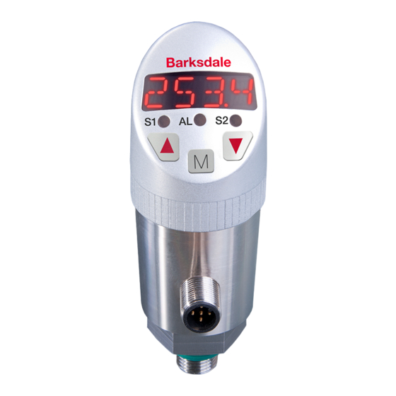
After having been switched on the switch runs through a self-test. If the software recognizes an
error during the self-test or during operation, this is signalled in the display by "Err" and the
corresponding message, refer to Error list on page 7. The red LEDs S1 and S2 signal the activity
of the two switching points.
Operation is menu-driven via three keys:
NC
Do not use any pointed, hard objects for making entries. The keys may be damaged by pointed,
hard objects.
NO
For information about the factory settings for the parameters and how to change them please refer
-
to the next chapter 8 "Programming".
7
IO-Link version
General Information
This unit has an IO-Link communication interface which requires an IO-Link-capable module
(IO-Link master) for operation. The IO-Link interface enables direct access to the process and
diagnostic data and provides the possibility to set the parameters of the unit during operation.
In addition communication is possible via a point-to-point connection with a USB adapter cable.
Device-specific information
You can find IODDs necessary for the configuration of the IO-Link unit and detailed information
about process data structure, diagnostic information and parameter addresses under
www.io-link.com ->IODD finder.
8
Programming
Navigation function
Menu descending
Menu ascending
Horizontal movement in menu, select menu item
Parameter change ascending
Parameter change descending
Accept parameter change and return to current menu item
Return to measured value display
WARNING
,
and
CAUTION
Symbol (keys)
Press
+
simultaneously
5
