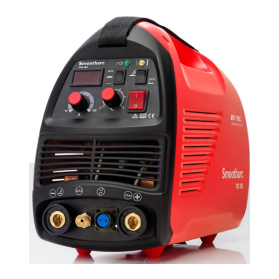
BOC Smootharc TIG 185 DC Manuel d'utilisation - Page 7
Parcourez en ligne ou téléchargez le pdf Manuel d'utilisation pour {nom_de_la_catégorie} BOC Smootharc TIG 185 DC. BOC Smootharc TIG 185 DC 15 pages. Boc smootharc tig 185 dc welder
Également pour BOC Smootharc TIG 185 DC : Manuel d'entretien (19 pages)

12
BOC Smootharc TIG 185 Operating Manual
Tungsten tip preparation
DCSP (EN) or DCRP (EP)
= Diameter
Flat
1/4–1/2x Dia
Taper length
2–3x Dia
ACHP General Purpose
Max. ball
1x Dia
Ball tip by arcing on clean metal at low current DCRP
(EP) then slowly increase current to form the desired ball
diameter. Return setting to AC.
Tungsten extension
Standard Parts
General
purpose
3x Dia
Tungsten electrode tip shapes and current ranges
Thoriated, ceriated, and lanthanated tungsten electrodes do not ball as readily as pure or zirconiated
tungsten electrodes, and as such are typically used for DCSP welding. These electrodes maintain a ground
tip shape much better than the pure tungsten electrodes. If used on AC, thoriated and lanthanated
electrodes often spit. Regardless of the electrode tip geometry selected, it is important that a consistent
tip configuration be used once a welding procedure is established. Changes in electrode geometry can
have a significant influence not only on the weld bead width, depth of penetration, and resultant quality,
but also on the electrical characteristics of the arc. Below is a guide for electrode tip preparation for a
range of sizes with recommended current ranges.
Electrode diameter
Diameter arc tip
(mm)
(mm)
1.0
0.125
1.0
0.250
1.6
0.500
1.6
0.800
2.3
0.800
2.3
1.100
3.2
1.100
3.2
1.500
Tungsten grinding
Shape by grinding longitudinally
(never radially). Remove the
sharp point to leave a truncated
point with a flat spot. Diameter
of flat spot determines amperage
capacity (See below). The
included angle determines weld
bead shape and size. Generally,
as the included angle increases,
penetration increases and bead
width decreases. Use a medium
(60 grit or finer) aluminium
oxide wheel.
Gas Lens Parts
General
purpose
3x Dia
Maximum
6x Dia
(in draft free areas)
Constant included
Current range
angle, (degrees)
(A)
12
2 – 15
20
5 – 30
25
8 – 50
30
10 – 70
35
12 – 90
45
15 – 150
60
20 – 200
90
25 – 250
2.7 Welding techniques
Vertical
Welding Rod
Shield gas
15–30°
Tungsten electrode
Direction of travel
2.8 Torch movement during welding
Tungsten Without Filler Rod
Welding
direction
Form pool
Tungsten With Filler Rod
Welding
direction
Form pool
90°
90°
Remove rod
2.9 Positioning torch tungsten for various weld joints
Butt Weld and
Stringer bead
'T' Joint
20°
70°
90°
90°
20°
20°
20°
10°
10°
BOC Smootharc TIG 185 Operating Manual
The suggested electrode and welding rod angles
for welding a bead on plate. The same angles are
used when making a butt weld. The torch is held
60–75° from the metal surface. This is the same as
60–75°
holding the torch 15–30° from the vertical.
Nozzle
Take special note that the rod is in the shielding
gas during the welding process.
75°
75°
75°
75°
75°
75°
90°
Tilt torch
Move torch to front of pool. Repeat.
20°
75°
75°
75°
75°
75°
75°
90°
75°
75°
15°
15°
70°
90°
15°
15°
20°
20°
10°
Tilt torch
90°
20°
20°
70°
75°
75°
90°
70°
75°
Move torch to front of pool. Repeat.
15°
20°
20°
10°
15°
70°
10°
90°
20°
20°
Corner Joint
20-40°
15°
70°
90°
75°
75°
10°
75°
90°
15°
15°
15°
15°
20°
30°
75°
13
90°
70°
90°
70°
20°
20°
20°
90°
20°
20°
10°
70°
75°
75°
15°
15°
15°
15°
10°
Add filler metal
20°
90°
70°
75°
75°
20°
15°
75°
90°
75°
10°
15°
15°
15°
15°
20-40°
75°
90°
75°
20-40°
Lap Joint
15°
75°
75°
30°
75°
15°
15°
30°
20-40°
75°
