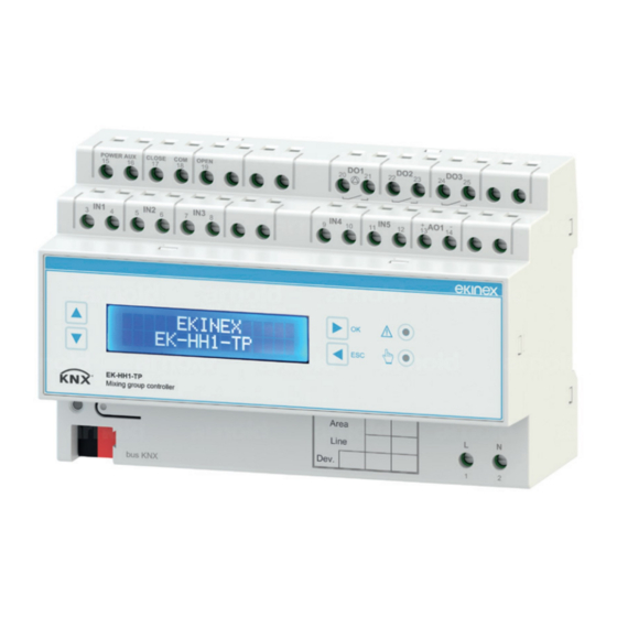
Ekinex EK-HH1-TP Manuel - Page 3
Parcourez en ligne ou téléchargez le pdf Manuel pour {nom_de_la_catégorie} Ekinex EK-HH1-TP. Ekinex EK-HH1-TP 4 pages. Controller for mixing group

POWER AUX
CLOSE
COM
OPEN
15
16
17
18
19
IN1
IN2
IN3
3
4
5
7
6
8
EK-HH1-TP
Mixing group controller
bus KNX
+
KNX
bus
-
L
230 Vac
50/60 Hz
N
Connection of power supply
The connection of the 230 Vac 50/60 Hz power supply is
made with the screw terminals 1 and 2 (L, N) located at
the bottom front of the device.
Characteristics of the terminals
• screw clamping of conductors
• maximum cross section of conductor 2.5 mm²
• recommended wire stripping approx. 6 mm
• torque max 0.5 Nm
Warning! The electrical connection of the device
!
can be carried out only by qualified personnel. The
incorrect installation may result in electric shock or
fire. Before making the electrical connections, make
sure the power supply has been turned off.
Connection of servomotor
3 point floating servomotor
The connection of the servomotor is made with the termi-
nals 17, 18 and 19 (CLOSE / COM / OPEN); it is neces-
sary also the connection of a 230 Vac or 24 Vac auxiliary
power supply with the screw terminal blocks 15 and 16
(POWER AUX).
Auxiliary power supply
(24 Vac or 230 Vac)
CLOSE
OPEN
COM
POWER AUX
CLOSE
COM
OPEN
15
16
17
18
19
IN1
IN2
IN3
3
4
5
6
7
8
DO1
DO2
DO3
20
22
24
21
23
25
IN4
IN5
+
AO1
-
9
10
11
12
13
14
OK
ESC
Area
L
N
Line
Dev.
1
2
M
DO1
DO2
DO3
20
21
22
23
24
25
+
-
IN4
IN5
AO1
9
10
11
12
13
14
Servomotor with 0...10 V control signal
The connection of the servomotor is made with the termi-
nal blocks 13 and 14 (AO1).
POWER AUX
CLOSE
COM
OPEN
15
16
17
18
19
IN1
IN2
IN3
3
5
7
4
6
8
Connection of circulating pump
The connection of the circulating pump is made with the
terminal blocks 20 and 21 (DO1).
L
230 Vac
50/60 Hz
N
POWER AUX
CLOSE
COM
OPEN
15
17
16
18
19
IN1
IN2
IN3
3
4
5
7
6
8
Connection of temperature sensors
The connection of the temperature sensors has to be
done respectively to the following terminal blocks:
• 3 and 4 (IN1) for fluid delivery temperature (T
• 5 and 6 (IN2) for fluid return temperature (T
• 7 and 8 (IN3) for external air temperature (T
POWER AUX
CLOSE
COM
OPEN
15
17
16
18
19
IN1
IN2
IN3
3
4
5
7
6
8
T
M
!
Warning! Use exclusively NTC temperature sen-
sors 10 kΩ at 25°C (ß = 3435). The maximum di-
stance between sensors and device cannot be lon-
ger than 10 m.
3
DO1
DO2
DO3
20
22
24
21
23
25
IN4
IN5
+
AO1
-
9
10
11
12
13
14
+
M
–
Control
board
DO1
DO2
DO3
20
21
22
23
24
25
IN4
IN5
+
AO1
-
9
10
11
12
13
14
)
D
)
R
)
E
DO1
DO2
DO3
20
21
22
23
24
25
IN4
IN5
+
AO1
-
9
10
11
12
13
14
T
E
T
R
