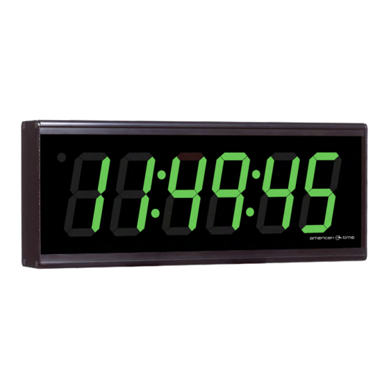
American Time SiteSynq IQ Manuel d'installation et d'utilisation - Page 17
Parcourez en ligne ou téléchargez le pdf Manuel d'installation et d'utilisation pour {nom_de_la_catégorie} American Time SiteSynq IQ. American Time SiteSynq IQ 19 pages. Wireless digital clocks

Wireless Digital Clocks Owner's Manual
Wireless Digital Clocks Owner's Manual
The ATSTCS Control Station can be mounted to a double gang box, 11/2
inch deep or deeper. The Control Station can be mounted up to 30 feet away
from the Digital Clock/Timer. The recommended minimum interconnecting
field wire size is #22.8 AWG stranded wire.
Ensure that installation conforms to the National Electrical Code and
local wiring codes.
CAUTION: Electric Shock Hazard! Ensure that NO electrical power is
present on any wire before installation.
1. Pull interconnecting field wires into the double gang box.
2. Connect field wiring interconnecting the ATSTCS Control
Station with the Digital Clock/Timer to the appropriate
wires of the Control Station. See wiring detail below.
3. Mount the Control Station to the double gang
box using the machine screws provided.
4. Terminate
1. START/STOP/
INCREMENT – Yellow Wire
2. ETI UP – Brown Wire
3. ETI DOWN – Blue Wire
4. SET/RUN – Orange Wire
5. RESET/ENTER – Grey Wire
6. 12V – Red Wire
7. PIEZO – Violet Wire
8. GND – Black Wire
12VAC/DC TO 30VAC/DC
NORMALLY-OPEN
SWITCHED CIRCUIT
SUPPLIED FROM CODE BLUE
CODE BLUE
UNIT
© American Time
© American Time
POWER ON
UNIT.
Appendix A: Optional Timer Control Station
ETI Control Station
8
1
–
+
RESET
PIEZO
ENTER
BUZZER
ATSTCS Wiring DIagram
WALL
Pre-drilled hole
Figure 1
SET
RUN
START/STOP
INCREMENT
Installation
17
