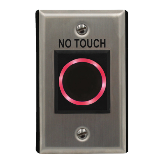
Door Controls DC10326 Manuel - Page 2
Parcourez en ligne ou téléchargez le pdf Manuel pour {nom_de_la_catégorie} Door Controls DC10326. Door Controls DC10326 4 pages. Indoor no-touch wave sensor

Parts List:
1 - No-Touch Sensor
Specifications:
Operating Voltage
Current draw (max.)
Relay type
Response time
LEDS Standby
LEDS Triggered
Output time
Sensing range
Operating temperature
Weight
*Default, reversible by jumper
Installation:
1. Run four wires through the wall to a single-gang back-box provided.
2. Connect the four wires from the back-box to the quick connect
screw-less terminal according to Fig. 1.
3. Screw the plate into the back-box, taking care not to crimp the wires.
4. Remove clear protective film from the sensor before use.
Adjusting the LED Color:
1. The LED color factory default setting is red (standby) and green
(triggered).
2. To reverse the LED color visual indicator to green (standby) and red
(triggered), remove the jumper located at the right side of the terminal
block as shown in Fig. 2.
Adjusting the Sensor Range and Output Timer
1. To adjust the sensor' s range, turn the trimpot counter-clockwise
(decrease) or clockwise (increase).
2. To adjust the output time, turn the trimpot counter-clockwise (de
crease) or clockwise (increase). To set to toggle, turn the trimpot all the
way counterclockwise.
321 VZ County Road 4500 · Ben Wheeler, TX 75754 · 800.437.3667 · DoorControlsUSA.com
2 - Mounting Screws
12-24 VAC/VDC
120mA@12VDC
Form C dry contact, 3A@24VDC
Adjustable, 0.5-30 sec., toggle, or as long as
sensor is triggered
Adjustable, 2 3 /8" - 8" (6-20 cm)
-4°~131° F (-20°~55° C)
3-oz (85g)
1 - Manual
1 - Single Gang Box
10ms
Red*
Green*
