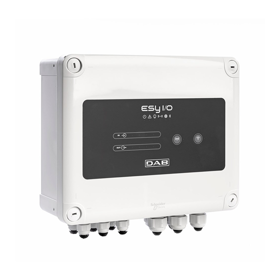
DAB ESY I/O Instructions pour l'installation et l'entretien - Page 9
Parcourez en ligne ou téléchargez le pdf Instructions pour l'installation et l'entretien pour {nom_de_la_catégorie} DAB ESY I/O. DAB ESY I/O 16 pages.

In the event of a momentary disconnection of the associated device, the blue LED will flash to indicate that the device is not connected, but is
trying to restore the connection.
The wireless network configuration is maintained even in the case of a temporary power cut or if the device is switched off.
Disconnection procedure and resetting of the wireless configuration.
Hold down the
key for 5 seconds. If the operation has been successful the blue LED will be off.
2.7 Optoisolated digital inputs
ESY I/O has the possibility to connect up to 4 optoisolated inputs.
The 4 digital inputs are optoisolated, they can be energised either with continuous negative and positive voltages or with alternating current at
50-60 Hz. Table 2 describes the characteristics and the limits of the digital inputs:
Minimum switch-on voltage [V]
Maximum switch-off voltage [V]
Maximum admissible voltage [V]
Current absorbed at 12V [mA]
Max. accepted cable section [mm²]
The optoisolated terminals are connected by applying a voltage to the terminals or by connecting the common signal to GND as a jumper and
connecting the I
signal to a contact (e.g. float, pressure switch, etc.)
n
Input wiring
Input
I1
I2
I3
I4
Below, Figure 4: Example of clean contact connectionFigure 4, an example of clean contact wiring on I1.
For the configuration of the inputs (e.g. Float Pressure Switch, Disable, etc.), refer to the manual of the device connected to ESY I/O.
The input status is displayed both by the Input LEDs (see Table 1), and on the APP Status page (see Figure 5).
ENGLISH
Characteristics of the inputs
DC inputs [V]
Table 2: input characteristics
Input connected to clean contact
Clean contact between
pins
I1-V+
I2-V+
I3-V+
I4-V+
Table 3: Input wiring
Figure 4: Example of clean contact connection
18
AC inputs 50-60 Hz [Vrms]
6.2
2
40
1.4
1.5
Jumper
C1/2 - CM
C1/2 - CM
C3/4 - CM
C3/4 - CM
4.5
1.5
40
1.4
Voltage input
Connection
I1 – C1/2
I2 - C1/2
I3 – C3/4
I4 – C3/4
