DoorHan PCB-SH Manuel d'instructions de programmation - Page 8
Parcourez en ligne ou téléchargez le pdf Manuel d'instructions de programmation pour {nom_de_la_catégorie} DoorHan PCB-SH. DoorHan PCB-SH 12 pages. Control board
Également pour DoorHan PCB-SH : Manuel d'instructions de programmation (14 pages), Manuel d'instructions de programmation (16 pages)
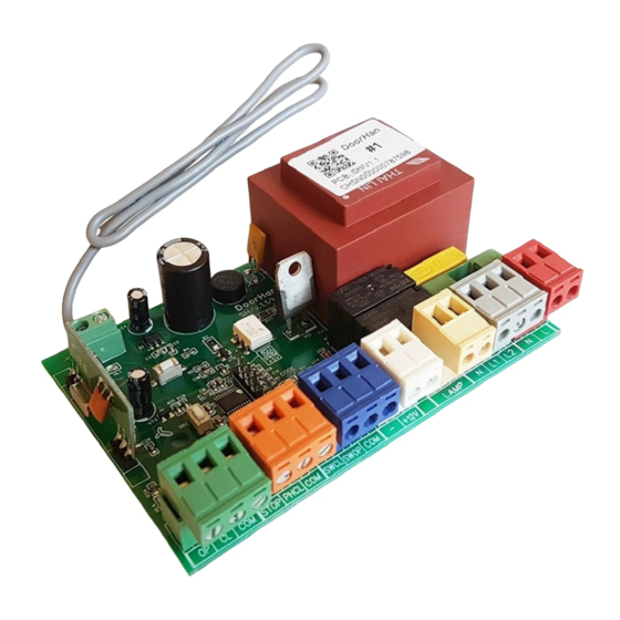
Type
Colour
Control devices
Green
Safety devices
Orange
Connection of limit
Blue
switches
Contacts of
White
accessories power
Additional accessories
Yellow
Power of motor
Grey
Power of board
1.2. ACCESSORIES WIRING DIAGRAMS
Fig. 2. Wiring diagram of 3-button control station, photocells and wicket door sensor
8
Terminals
Jack
№
1
ХP9
2
3
1
ХP7
2
3
1
ХP3
2
3
1
ХP8
2
1
ХP6
2
1
ХP2
2
3
1
Red
ХP1
2
Meaning
Full opening command. After closing of contacts of the device connected to
Open
this terminal, the control unit will trigger either full opening of the door or
stepped control of operator (depending on the preset control logic)
Close command. After closing of contacts of the device connected to this
Close
terminal, the control unit will trigger door closing
Com
Common contact
Stop command. After breaking of contacts of the device connected to this
STOP
terminal, the control unit will stop door movement
Contacts for safety device connection (NC). Safety devices are used to prevent
people, animals and foreign objects from being jammed in the door opening
PH CL
by the moving door leaf. Activation of safety devices immediately stops or
reverses the door. If the door is open and the sensors connected to these
terminals are triggered, this will prevent any movement of the door
COM
Common contact
SW CL
Connection of limit switch regulating down travel limit (limit switch red wire)
SW OP
Connection of limit switch regulating up travel limit (limit switch green wire)
COM
Common contact (limit switch white wire)
(-)
Unstable voltage 24 V
+
LAMP
Signal lamp (~ 220 V) terminals are available on pcb 1.1 only
N
Electric motor common terminal
L1
Electric motor closing terminal
L2
Electric motor opening terminal
N
Mains supply (~ 220 V) connection
L
ELECTRIACAL CONNECTIONS
Table 2. Control unit terminals
Connecting devices