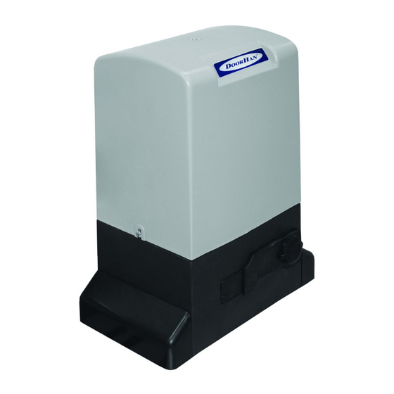
DoorHan SLIDING-2100 Manuel d'installation et d'utilisation - Page 8
Parcourez en ligne ou téléchargez le pdf Manuel d'installation et d'utilisation pour {nom_de_la_catégorie} DoorHan SLIDING-2100. DoorHan SLIDING-2100 16 pages. Drive
Également pour DoorHan SLIDING-2100 : Manuel d'installation et d'utilisation (12 pages), Manuel d'installation et d'utilisation (12 pages)

5.
eLeCtRICAL ConneCtIons
5.1. Control unit electric diagram
AttentIon! Turn off the power supply before beginning work with control board. The power cables must be laid
separate from signal cables. To reduce induced noises, use cables with screened armature. Cable wires must be
protected from contact with rough and sharp parts.
Connection of photocells for close.
If you use DoorHan PhotoCell photocells, put the jumper in NC position
LED3
NO
NC
Connection of photocells for open.
If you use DoorHan PhotoCell photocells, put the jumper in NC position
LED3
NO
NC
5.2. Description of the control unit elements
Control unit elements
TR1
J1
Dip
FUSE
FUSE2
TIMER W
AUTO CL
FORCE
Control unit connectors
~220 (N, L, pE)
Motor (N, L1,L2)
Lamp
—
+24V
Sw Op
Sw Cl
EMRG
ph Op
ph Cl
ped
Start
8
Radio receiver
r
Jumpers
Limit switches
Connector for quick connection of radio receiver
Regulator of pause before automatic close
Connector for motor connection
Connector for connection of signal lamp (see the diagram)
Negative contact of power supply for accessories (24 V) 600 mA
positive contact of power supply for accessories (24 V) 600 mA
Control contact of open limit switch
Control contact of close limit switch
pair of emergency stop contacts (NC)
Control contact of open photocells (NC)
Control contact of close photocells (NC)
Close command (Dip2 is on) (NO)
Open or stepped control command (NO)
electrIcal cOnnectIOns
Capacitor
Lamp-Led
Transformer
Group of DIp switches
High voltage part fuse
Low voltage part fuse
Motor run time regulator
pulling force regulator
Supply voltage
GND
