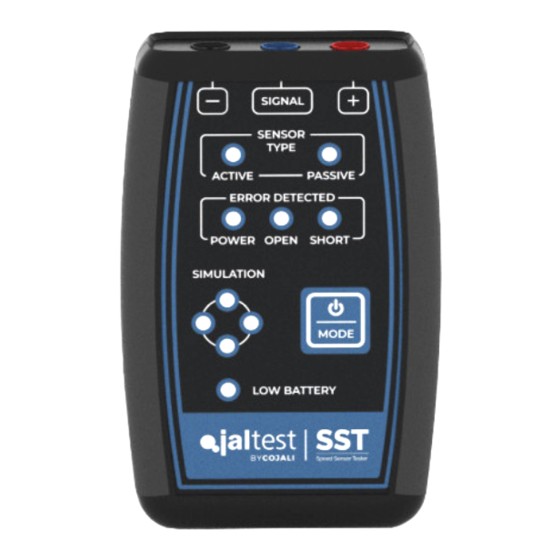
Cojali Jaltest SST Manuel de l'utilisateur - Page 9
Parcourez en ligne ou téléchargez le pdf Manuel de l'utilisateur pour {nom_de_la_catégorie} Cojali Jaltest SST. Cojali Jaltest SST 15 pages. Speed sensor tester

the help of a diagnosis device that shows the speed read by the ECU, the user will
be able to detect errors in the wiring or in the control unit itself.
1
Disconnect the speed sensor from the vehicle and connect instead the Jaltest SST
device through multipin cable kit according to the
diagram section
(it is possible to connect multipins to the ECU or to an intermediate
connector).
2
Turn on the device and go into
selection button of the mode (1) according to the presses described in the
table
on page 6. The
LED of the errors that may appear.
Note: In case that the short circuit error appears in the Jaltest SST device, it can be removed once step
3 is being carried out with just a short press of the selection button of the Mode.
3
Turn the ignition key of the vehicle to the ignition key position.
4
Use a diagnosis software to
verify that the ECU is reading
the speed simulated by the
device (if you do not have a
diagnosis device, go to step 5).
If the ECU is not reading the
speed, perform short presses
of the selection button of the
mode (1) to reset the present
errors and adjust the signal
frequency gradually so that it
can be read by the ECU:
Note: The speed read depends on the vehicle ECU and can vary significantly depending on it.
5
Error check:
ٚ The
power supply error
cable or the ECU does not provide the appropriate voltage for this cable.
ٚ The
short circuit error
supply has occurred during the execution of the test.
Active Sensor Simulation
Simulation
and
Active sensor
No. of presses
Start (go into
Simulation
LED lights up: There is an error in the sensor power supply
LED lights up: Short circuit to ground (chassis) or power
IMAGE 3
of the connection
mode interacting with the
LEDs must be on, as well as the
Signal frequency (Hz)
Active Sensor
mode)
1
2
3
4
9
English
function
50
166
333
498
760
