bolid S2000-KPB Manuel d'instruction
Parcourez en ligne ou téléchargez le pdf Manuel d'instruction pour {nom_de_la_catégorie} bolid S2000-KPB. bolid S2000-KPB 17 pages. Executive module
Également pour bolid S2000-KPB : Manuel d'instruction (14 pages)
1.1 General
1.2 1. This Instruction Manual describes how to operate and maintain the S2000-KPB Executive
Unit of version 3.02 (hereinafter referred to as the unit).
1.2 2. The unit is designed to be used with an S2000M panel, an S2000-ASPT fire alarm and
extinguishing control unit, or a PC as a component of modular control and indicating equipment in
such system as a fire / intrusion / panic alarm system, a voice alarm and evacuation system, a fire
suppression system, an access control system, or a CCTV system.
1.2 3. The unit is designed to control executive devices (light panels, light alarms, sirens, video
cameras, electromagnet locks etc.) as well as clean agent suppression systems and fire-fighting
equipment in gas, dry powder, and aerosol fire-fighting systems. The unit controls executive devices
by switching voltage from its power input terminals U
external power supplies to output terminals is prohibited and can damage the unit.
1.2 4. The unit is designed to be installed on a vertical surface inside the protected premises
closely to the executive devices. The unit is designed for round-the-clock operation.
1.2 5. The unit must not be used in aggressive medium or dust condition, or in explosion-
hazardous premises.
1.2 6. As to the resistance to mechanical stress, the unit falls in the placement category 03 of ОСТ
25 1099-83.
1.2 7. As to immunity to climate effects of environment, the unit corresponds to version 03 in
accordance with ОСТ 25 1099-83 but for ambient temperatures from minus 30 to +55°С.
1.2 Specifications
1.2 1. Power Supply:
1.2 2. Power Inputs:
1.2 3. Consumed Current
(without executive devices):
1.2 4. Outputs:
− Switching Voltage:
− Switching Current:
− Circuit Failure Monitoring Current:
1.2 5. Max Total Switched Current of the Unit:
1.2 6. Inputs:
1.2 7. Resistance of the loop wires
without termination resistance:
1.2 8. Leakage resistance between the loop wires
or each wire and ground:
1.2 9. Overall Dimensions:
1.2 10. Weight:
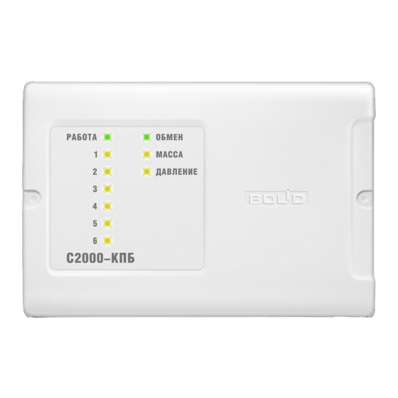
S2000-KPB
EXECUTIVE UNIT
Version 3.02
INSTRUCTION MANUAL
1
TECHNICAL DESCRIPTION
and U
to its output terminals. Connecting
main
back
An external dc power supply with power
voltage between 10.2 V dc and 28.4 V dc
(RIP-12, RIP-24)
Two
100 mA max
Six
10.2 dc to 28.4 V dc (from the power
supply of the unit) ;
5 mA ÷ 2.5 A;
1.5 mA max
6 A
Two
100 Ohm max
At least 50 kOhm
156 mm × 107 mm × 39 mm max
0.3 kg max
1