bolid IPR 513-3M Manuel d'instruction
Parcourez en ligne ou téléchargez le pdf Manuel d'instruction pour {nom_de_la_catégorie} bolid IPR 513-3M. bolid IPR 513-3M 2 pages.
Également pour bolid IPR 513-3M : Manuel de conversation (15 pages)
1.1
General
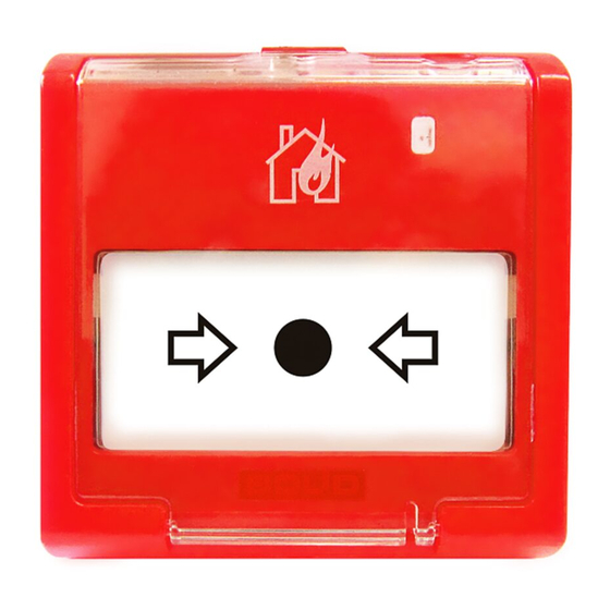
IPR 513-3M Resettable Manual Call Point (hereinafter referred to as the call point or the IPR 513-3M) is designed to be used in fire
alarm systems and fixed fire-fighting systems to manually release fire alarms or activate the system respectively.
The IPR 513-3M is to be powered through an alarm loop of such control and indicating equipment (hereinafter referred to as the
CIE) as S2000-4, Signal-20P, S2000-ASPT, Signal-10, Signal-20M or similar that provides a voltage up to 30 V within the alarm
loop and limits the current in the loop up to the level of 25 mA.
The flip transparent protective cover of the IPR 513-3M can be sealed with an intact control seal.
The manual call point is intended for round-the-clock operation and classified as a repairable and periodically maintained item.
1.2
Specifications
1) Commuted Voltage
2) Commuted Current
3) Current Consumed in Quiescent Mode
4) Ingress Protection Rating
5) Operating Temperatures
6) Relative Humidity
7) Transportation / Storage Temperatures
8) Overall Dimensions
9) Weight
10) The content of precious materials: doesn't require accountability for storage, retirement, and disposal.
11) The content of non-ferrous metals: does not require accountability for retirement and further disposal.
2.1
Wiring
Figure 1 shows a typical diagram for connecting IPR 513-3M. While connecting a manual call point to a CIE, please be guided by
the user's manual for the CIE in use and the diagram for connecting the manual call points to this CIE.
1
1 – Control and indicating equipment (CIE),
2, 3 – IPR 513-3M manual call points,
4 – An end-of-line device (resistor, diode, etc.)
The quiescent mode of the IPR 513-3M is indicated by single flashing of its built-in LED
once per 4 seconds.
Once the manual call point is activated, its LED starts showing solid light confirming that the
CIE has received the signal from the IPR 513-3M. In this process the IPR 513-3M decreases
its internal resistance down to 500 Ohm max.
2.2
Mounting
The IPR 513-3M is to be mounted using the two screws provided to a flat vertical surface in
line with Buildings Codes and Regulations.
The wires which pass under the IPR 513-3M should not be clamped by the IPR 513-3M
housing.
Figure 2 shows the view of the IPR 513-3M (without the protective flip cover):
1: Hole to insert the housing key to reinstate the activated call point;
2: Holes to insert the housing key to release the front part of the call point housing;
3: The housing key to reset activated IPR 513-3M / to open its housing;
4: Place to apply an intact control seal.
RESETTABLE MANUAL CALL POINT
INSTRUCTION MANUAL
1 TECHNICAL DATA
- 30 V max
- 25 mA max
- 50 uA max
- IP40
- Minus 30°C to +55°C
- Up to 93% at +40°C
- Minus 30°C to +55°C
- 95 × 91 × 34 mm
0.15 kg max
2 OPERATION INSTRUCTIONS
–
+
+
+
-
2
Figure 1
IPR 513-3M
1.3
Scope of Delivery
For a group delivery:
– IPR 513-3M
– Instruction Manual
– Special Housing Key
– Woodscrew 1-4×30.20.019 GOST 1144-80 - 20 pcs.;
– Wall Plug 8×30
– Unit Package
– Group Package
-
1
4
+
+
-
-
3
Figure 2
- 10 pcs.;
- 1 copy;
- 10 pcs.;
- 20 pcs.;
- 10 pcs.
- 1 pc.