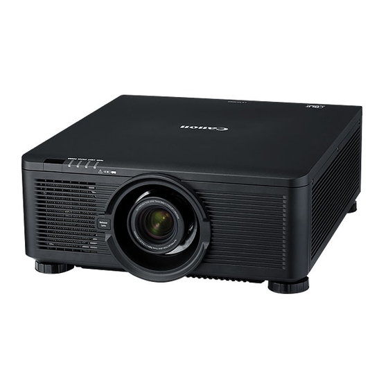
Canon LX-MU600Z Manuel - Page 6
Parcourez en ligne ou téléchargez le pdf Manuel pour {nom_de_la_catégorie} Canon LX-MU600Z. Canon LX-MU600Z 15 pages.

2-4. Adjustable foot
Adjustable foot 1
Adjustable foot 3
Twisting
* The figure is for explanation only and different from the actual product shape.
(6/14)
Adjustable foot 2
The figure on the left is a schematic diagram of the
bottom of the projector.
As shown in the figure, there are four adjustable
feet.
Adjusting the lengths of Adjustable feet 1 and 2
raises the projection direction while adjusting the
length of Adjustable feet 3 and 4 lowers the
projection direction.
Each adjustable foot can be used to make fine
adjustments to the horizontal slant of the projector.
Adjustable foot 4
The figure on the left is a schematic diagram of the
side of the projector.
All adjustable feet are a screw-type and their
heights can be adjusted by twisting.
Twisting
The projector can be set up at an angle of elevation
of up to 7 degrees between itself and the surface it
is placed on.
7°max
