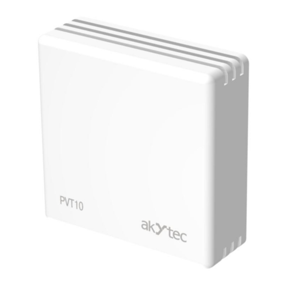
Akytec PVT10 Manuel de l'utilisateur - Page 7
Parcourez en ligne ou téléchargez le pdf Manuel de l'utilisateur pour {nom_de_la_catégorie} Akytec PVT10. Akytec PVT10 17 pages. Humidity and temperature transmitter

Installation
5
Installation
To ensure representative measurement of temperature and humidity in the room, choose
carefully the transmitter installation place. PVT10 should not be located at direct sunlight,
near heat sources or air conditioning units, near doors and windows, in places where air
circulation is limited, or on poorly insulated and cold external walls.
Detach the base from the enclosure by pulling gently along the four guiding pins (Fig.
5.1). Fix the base on the wall either by double-sided adhesive tape or by screws. You
may need to drill suitable holes or cutouts in the base for screws and cable.
Orient the transmitter with ventilation slots upwards and downwards to ensure proper air
convection for faster response and higher accuracy. Plug the power cable and connect
the analog outputs or digital interface terminals to the relevant devices (Fig. 5.2). PVT10
uses screwless quick connect spring terminals suitable for wide range of wire cross-
sections 0.2...1.5 mm
spring loaded terminal lever, insert the wire end into terminal hole and release the lever.
The type of each analog output can be independently changed between 4-20 mA and
0-10 V with jumpers J1 (OUT1) and J2 (OUT2):
akYtec GmbH · Vahrenwalder Str. 269 A · 30179 Hannover · Germany · Tel.: +49 (0) 511 16 59 672-0 ·
Fig. 5.1 Device mounting
2
. The recommended wire stripping length is 8...9 mm. Push the
closed jumper: 0-10 V
opened jumper: 4-20 mA
Fig. 5.2 Wiring
www.akytec.de
6
