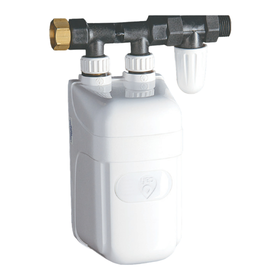
dafi IPX4 Manuel d'utilisation - Page 11
Parcourez en ligne ou téléchargez le pdf Manuel d'utilisation pour {nom_de_la_catégorie} dafi IPX4. dafi IPX4 13 pages. Electric a flow heater with an open outlet water
Également pour dafi IPX4 : Instructions pour l'installation et l'utilisation (12 pages)

NOTES ON INSTALLATION OF DAFI WATER HEATERS
DAFI energy saving water heaters can be installed above, or under your basin or sink. Shower installations are also possible, but never
inside the shower cubicle. Installation of your water heater in the ceiling or behind the wall, or in a cupboard next to the shower should be
considered.
DAFI water heater Installation Requirements:
1. DAFI water heaters must be installed as close to the point of use as possible to minimise pipeline heat loss.
2. Water pressure must not be less than 60kPa (0.6 bar) and not exceed 600kPa (6bar). If water pressure is too high, a pressure reducing
valve must be installed.
3. Water quality e.g. mains supply, borehole, river etc. Should water quality be suspect, a filter must be installed.
4. Single phase or 3 phase power supply with own isolator switch must be available as close as possible to point of usage.
DAFI water heater Installation Procedure:
Installing the DAFI energy saving water heater is not complicated, but it needs to installed by a professional plumber and
electrician for problem-free operation.
Water supply:
• To be undertaken by a qualified Plumber
• Incoming water supply should be clean and without any suspended solids or organic materials.
• The "static" incoming cold water supply pressure to be accurately measured to ascertain operating conditions.
1. contacts
• The maximum operating pressure of all DAFI Heater models is 600 kPa (6 Bar).
• A suitable Pressure Reducing Valve is to be installed before the heater unit, should this 600 kPa limit be exceeded.
• Heater manifold nut assembly must only to be tightened with the spanner supplied in each box.
2. base
• All air to be vented from the heater unit prior to connecting the 240 volt or 400 volt 50 Hz power supply.
• A cut-off valve should be installed on the water inlet line to the DAFI heater.
3. housing
• All heater units for under sink installation can be installed at any angle.
4. heating element
Recommendations:
• Installing a composite pipe from your DAFI water heater to the point of usage will further reduce heat loss and save more energy.
• For optimum performance enhancement Spray Nozzle provided should be attached to tap. For models 3.7 kW & 4.5 kW
5. tap
Spray Nozzle is highly recomended. Spray Nozzle spread water and rise pressure of hot water.
• Beware of over tightening , use plastic key provided. Do not use metal spanner!
6. spout
• For performance see table FT - flow/temperature
7. connection wire
Tips:
1.Each installation is indywidual. Performance of Dafi Heater depends on: voltage drop, temperature of cold water, pressure , type of taps,
distance of instalation from point of use, etc. Selection of right power should be done by experienced and competent trade person.
2. Before you buy check if obtained flow corresponds to your demands.
Electric supply:
To be undertaken by a qualified Electrician
1. Each heater unit is to be wired to the Distribution Board via the existing Earth Leakage System.
Minimum 3 core cable sizes*
- 2.5mm² for 3.7 kW & 4.5kW (240V)
- 4 mm² or 2x2.5mm²(ring) for 5.5 kW & 7.3kW - (240V)
- 2.5mm² for 7.5kW these models is two phase no neutral -(400V)
- 4 mm² 9 kW & 11kW these models are two phase no neutral -(400V)
*size of cable need to be confirmed with installation method and voltage drop
2. Models 7.5 kW - 11kW are non-domestic unles three phase supply system in property.
Any combination of two phases no neutral (eg brown/black=400V).
3. A dedicated suitably sized breaker to be installed on the Distribution Board for each heater unit.
4. A suitable sized 2 pole electric isolator (not fuse spur) to be installed.
5. DAFI heater units are not to be connected to the electrical supply by standard BS 1363 wall plug.
FT - flow/temperature
SPECIFICATIONS
[kW]
Rated power consumption
[~V]
Rated voltage
[A]
Rated current
[A1]
Automatic breaker
[B1]
Water
liters / the minimum
temperature of owing water
15°C and pressure 200 000 Pa
≤ 1300 cm - 15°C
40°C
ciency measured in
45°C
1. base
2. long contacts
3. housing
4. short contacts
5. connector nut
6. connection wire
7. connector
8. connector seal
3.7
4.5
5.5
1/N/PE~ 240V 50Hz
16
19.6
24
16
20
25
1.9
2.4
2.9
1.7
2
2.5
9. heating element
10. membrane
tappet
11. membrane
12. membrane
cover
13. oring
14. ceramic pipe
7.3
7.5
9
2/PE~ 400V 50Hz
31.7
18.75
22.5
32
20
25
4
4
4.7
3.3
3.3
4
11
25
32
5.8
5.1
