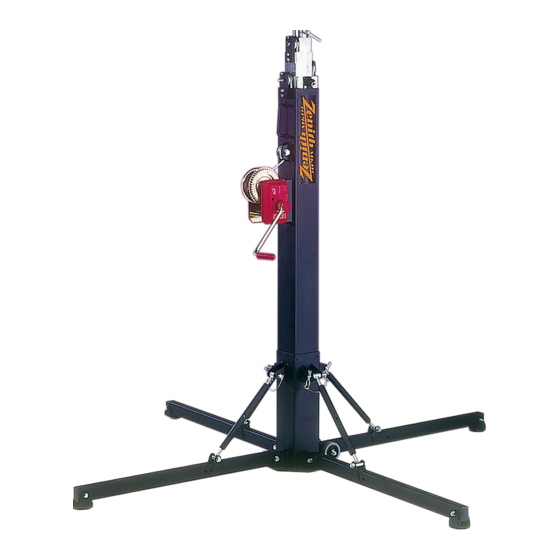
Doughty Zenith 520R Manuel d'utilisation - Page 6
Parcourez en ligne ou téléchargez le pdf Manuel d'utilisation pour {nom_de_la_catégorie} Doughty Zenith 520R. Doughty Zenith 520R 12 pages. Winch stand

Assembly
Roller Base:
1. Manoeuvre the stand to the desired location, ensuring the base of the stand is in
contact with the supporting surface.
2. Remove the legs from their transport position.
3. Insert the leg into the base leg receiver (see figure 4), ensuring the adjustable
foot is orientated to contact the supporting surface.
4. Turn the foot support to lower or raise the foot. The foot should be in firm contact
with the supporting surface.
5. Repeat the above actions for all four legs.
6. Once the legs are secured the load may be attached to the stand by using a
28mm TV spigot. This must be secured in the receiver by the Tommy Bar
provided (see figure 2).
7. To disassemble the stand prior to moving, perform the above actions in reverse
order.
Turnbuckle Base:
1. Manoeuvre the stand to the desired location and raise the mast to the vertical,
ensuring the base of the stand is in contact with the supporting surface.
2. Release the legs from their transport position by removing the R clip and locking
pin (see figure 5).
3. Rotate the legs about the pivot point, ensuring the pivot foot is orientated to
contact the supporting surface, and lock the turnbuckle into the leg support
bracket with the locking pin. Ensure the R clip retains the locking pin.
4. Repeat the above actions for all four legs.
5. Adjust the turnbuckles to centralise the spirit level and ensure the mast is
vertical. The base of the stand must remain in direct contact with the ground.
6. Once the mast section is vertical and the legs are secured the load may be
attached to the stand by using a 28mm TV spigot. This must be secured in the
receiver by the Tommy Bar provided (see figure 2).
7. To disassemble the stand prior to moving, perform the above actions in reverse
order.
Operation
Lifting:
1. To start raising the stand, pull and rotate the upper locking pin (figure 1) to locate
in the raise position (see figure 1) and rotate the winch handle (figure 2-8)
clockwise, as indicated on the body of the winch.
2. Once located in the raising position, the locking pin will operate on a ratchet
when the winch handle is turned and the stand is raised.
3. Continue winding the handle until the mast either stops moving (top of stroke), or
the desired height is achieved.
4. To release the next mast section, pull and rotate the locking pin to locate it in the
raise position (see figure 1).
5. Repeat steps 3 and 4 for the remaining section.
www.doughty-engineering.co.uk
Page 6 of 12
Issue: 04
Date: 05-03-13
