Baumer G0LMH Manuel - Page 21
Parcourez en ligne ou téléchargez le pdf Manuel pour {nom_de_la_catégorie} Baumer G0LMH. Baumer G0LMH 26 pages. Absolute encoder profibus-dpv0 (with bus cover and ssi coupler)
10. Terminal assignment and commissioning
10.1. Mechanical mounting
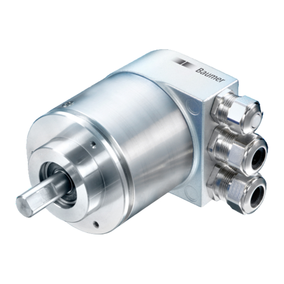
Shaft encoder
Mount the encoder housing using the fastening holes on the flange side with three screws (square flange
with four screws), paying attention to the thread diameter and thread depth.
Alternatively, the encoder can be mounted in any angular position using three eccentric fastenings - see
accessories.
Connect the drive shaft and encoder shaft using a suitable coupling. The ends of the shafts must not be
touching. The coupling must be capable of compensating for displacement due to temperature and
mechanical backlash. Pay attention to the admissible axial or radial shaft loads. For suitable connecting
devices, see under accessories.
Tighten the fastening screws
End shaft / Hollow shaft encoder
Clamping ring fixture
Prior to mounting the encoder open the clamping ring completely. Push encoder onto the drive shaft and
tighten the clamping ring firmly.
Encoder torque pin
Slide encoder onto the drive shaft and insert torque pin into the adjusting element provided by customer.
Adjusting element with rubberized spring element
Push the encoder on to the drive shaft and insert the parallel pin into the mounted adjusting element (not
supplied) (with rubberized spring element)
Adjusting bracket
Push the encoder over the drive shaft. Insert the adjusting bracket into the rubberized spring element of
the encoder and fasten the adjusting bracket on the contact surface (not supplied).
Shoulder screw
Push the encoder over the drive shaft and insert the shoulder screw (not supplied) in the rubberized spring
element of the encoder.
Coupling spring
Mount the coupling spring with screws onto the fixing holes of the encoder housing.
Push the encoder over the drive shaft and fasten the coupling spring on the contact surface.
10.2. Electrical connection
Only ever store or transport the bus cover in the ESD bag. The bus cover must rest fully against the housing
and be firmly screwed in place.
For electrical connection, pull off the bus cover using the following method:
Release the fastening screws of the bus cover
Carefully loosen the bus cover and lift off in the axial direction
10.2.1. Setting the user address
The user address is set decimally using two rotary switches in the bus cover.
The maximum number of users is 99. The address is read in once during power-up.
Set the user address decimally using the two rotary switches 1 and 2 (default setting 00).
Baumer_ProfibusDPV0_BIDE_MA_EN.docx
11.19
Example: 23
21/26
Baumer IVO GmbH & Co. KG
Villingen-Schwenningen, Germany