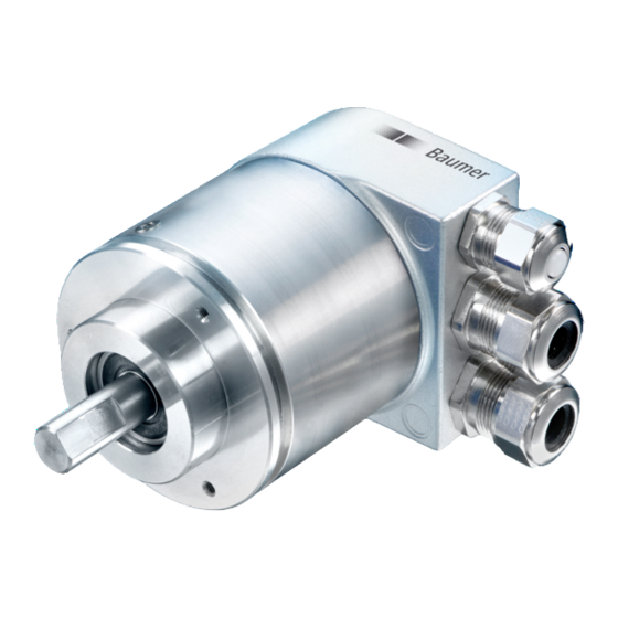
Baumer GXMMW Manuel - Page 15
Parcourez en ligne ou téléchargez le pdf Manuel pour {nom_de_la_catégorie} Baumer GXMMW. Baumer GXMMW 19 pages. Absolute encoder with powerlink interface
Également pour Baumer GXMMW : Manuel (41 pages), Manuel (26 pages), Manuel (24 pages), Manuel (19 pages)

6
Terminal assignment and commissioning
6.1
Mechanical mounting
Shaft encoders
• Mount encoder housing by help of the mounting holes and three screws (square flange: 4 screws)
provided at flange. Observe thread diameter and depth.
• There is an alternative mounting option in any angular position by eccentric fixings, see under
accessories.
• Connect drive shaft and encoder shaft by using an appropriate coupling. The shaft ends must not touch
each other. The coupling must equalize any shifts due to temperature as well as mechanical tolerances.
Observe the maximum permitted axial or radial shaft load. For appropriate couplings please refer to
accessories.
• Tighten the mounting screws firmly.
End shaft encoders
• Mounting by clamping ring
Open clamping ring completely before mounting the encoder.
Slide encoder onto the drive shaft and tighten the clamping ring firmly.
• Adjusting element with rubber buffer
Slide encoder onto the drive shaft and insert cylindrical pin into adjusting element (with rubber buffer)
provided by customer.
• Spring washer
Spring washer assembly at the encoder housing is by inserting the screws into the mounting holes. Slide
encoder onto the drive shaft and assemble spring washer at the contact surface.
6.2
Electrical connection
Assignment – M12 connector
Follow also the instructions of the respective supplier.
- Press mating connector softly into the plug.
- Turn mating connector carefully until the code mark is interlocking the corresponding space provided by the
plug. Insert bushing completely. Tighten the nut as far as possible.
Exchange bus cover
The bus cover is to be stored and transported whilst in the ESD bag only. The bus cover has to fit the case
tightly and has to be firmly secured by screws.
Remove bus cover
- Unscrew both fixing screws of the bus cover.
- Loosen bus cover carefully and remove it in axial direction.
Plug on bus cover
- Plug the bus cover carefully onto the D-SUB plug of the basic encoder, then push it over the rubber seal.
Avoid the case getting wedged. The bus cover has to fit tightly the basic encoder.
- Tighten both fixing screws firmly and conformable.
- An optimized connection between encoder case and the braiding shield of the supply cable is only achieved
by a complete and close fit of the bus cover onto the basic encoder (interlock).
Manual_EtherCAT_PoE_BIDE_EN.doc
11.11.10
15/19
Baumer IVO GmbH & Co. KG
Villingen-Schwenningen, Germany
