Baumer HOG 10 G Instructions de montage et d'utilisation - Page 29

Parcourez en ligne ou téléchargez le pdf Instructions de montage et d'utilisation pour {nom_de_la_catégorie} Baumer HOG 10 G. Baumer HOG 10 G 40 pages. Incremental encoder (twin encoder)
Également pour Baumer HOG 10 G : Manuel d'installation et d'utilisation (36 pages), Manuel d'installation et d'utilisation (40 pages), Instructions de montage et d'utilisation (32 pages), Instructions de montage et d'utilisation (36 pages), Instructions de montage et d'utilisation (36 pages)
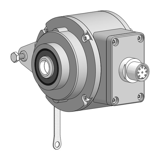
Baumer HOG 10 G Instructions de montage et d'utilisation
7.2

Ausgangssignale

Signalfolge bei positiver
Drehrichtung, siehe Abschnitt 6.
Sequence for positive rotating
direction, see section 6.
7.3

Klemmenbelegung

7.3.1
Standard
Max. 1,5 mm
Max. AWG 16
7.3.2
Option EMS
(Enhanced Monitoring System)
Max. 1,5 mm
Max. AWG 16
Betriebsspannung nicht auf Aus-
gänge legen! Zerstörungsgefahr!
Spannungsabfälle in langen Leitungen
berücksichtigen (Ein- und Ausgänge).
MB072T2 - 11070661
2
K0
K0
K2
K2
K1
K1
+UB
2
xxx
Err
K0
K2
K1
+UB
Baumer_HOG11-HOG11G-T2_II_DE-EN (17A2)
Elektrischer Anschluss / Electrical connection
7.2
Output signals
90°
7.3
Terminal assignment
7.3.1
Standard
Ansicht X
Anschlussklemmen,
siehe Abschnitt 5.12.
View X
Connecting terminal,
see section 5.12.
Zwischen
und
There is no connection between
7.3.2
Option EMS
(Enhanced Monitoring System)
Ansicht X
Anschlussklemmen,
siehe Abschnitt 5.12.
View X
Für/For Err
K0
Connecting terminal,
K2
see section 5.12.
K1
Zwischen
und
There is no connection between
Do not connect voltage supply to
outputs! Danger of damage!
Please, beware of possible voltage drop
in long cable leads (inputs and outputs).
K1
K1
K2
K2
K0
K0
besteht keine Verbindung.
and
besteht keine Verbindung.
and
7
.
.
26