Baumer Hubner Berlin HMG 11 Instructions de montage et d'utilisation - Page 9
Parcourez en ligne ou téléchargez le pdf Instructions de montage et d'utilisation pour {nom_de_la_catégorie} Baumer Hubner Berlin HMG 11. Baumer Hubner Berlin HMG 11 40 pages. Absolute encoder ethercat
Également pour Baumer Hubner Berlin HMG 11 : Manuel d'installation et d'utilisation (48 pages), Manuel d'installation et d'utilisation (40 pages), Instructions de montage et d'utilisation (36 pages)
3.
PREPARATION
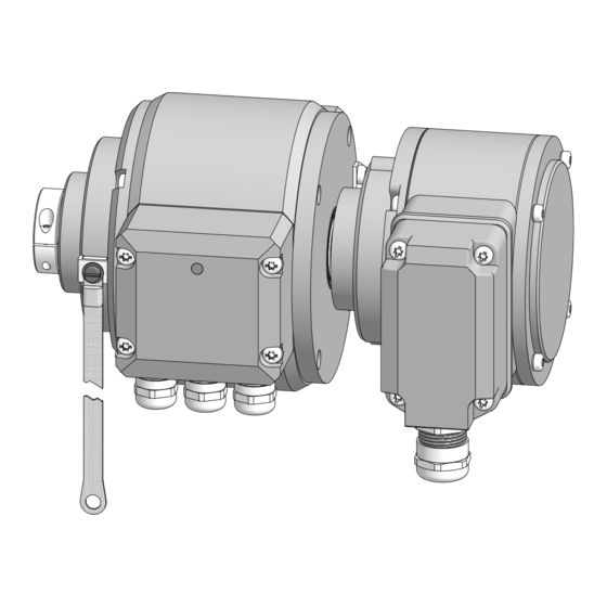
3.1
Scope of delivery
6d 6e 6f
6c
7b
[B]
1
Housing
2
Cover
3
Torx/slotted screw M4x10 mm, DIN 7964
4
LED function indicators
5
Earthing strap, length ~230 mm
Equipment for mounting a torque arm:
6a
Clamping ring adjustable through 360°
6b Torx/slotted screw M4x20 mm, ISO 7045
6c
Support plate
6d Hexagon screw M6x18 mm, ISO 4017
6e
Washer B6�4, ISO 7090
6f
Self-locking nut M6, ISO 10511
* Depending on version
MB244EN - 11171691, 19A2, Baumer_HMG10-SSI_II_EN
7a 6a 6b
1
5
8b
8c
8a
[D]
[C]
[A]
Blind hollow shaft* or cone shaft*:
7a
Blind hollow shaft or cone shaft with
spanner flat 17 a/f
7b Clamping element, not for cone shaft
Through hollow shaft*:
8a
Through hollow shaft
8b Clamping ring
8c
Torx screw M3x12 mm, ISO 7045
Radial terminal boxes* (see
[A] SSI
Additional output incremental 1 (option)
Programming interface (only HMG10P)
[B] Additional output incremental 2 (option)
Speed switch (option)
Radial flange connectors* (see section
[C] SSI
Additional output incremental 1 (option)
Programming interface (only HMG10P)
[D] Additional output incremental 2 (option)
Speed switch (option)
PREPARATION
2
3
7a
2
4
8a
section
5):
5):
4
5/35