Baumer HUBNER BERLIN HOG 10 Manuel d'installation et d'utilisation - Page 8

Parcourez en ligne ou téléchargez le pdf Manuel d'installation et d'utilisation pour {nom_de_la_catégorie} Baumer HUBNER BERLIN HOG 10. Baumer HUBNER BERLIN HOG 10 40 pages. Incremental encoder with connecting cable ölfle
Également pour Baumer HUBNER BERLIN HOG 10 : Manuel d'installation et d'utilisation (36 pages), Instructions de montage et d'utilisation (40 pages), Manuel d'installation et d'utilisation (40 pages), Instructions de montage et d'utilisation (40 pages), Instructions de montage et d'utilisation (40 pages), Instructions de montage et d'utilisation (32 pages), Instructions de montage et d'utilisation (36 pages), Instructions de montage et d'utilisation (36 pages), Instructions de montage et d'utilisation (28 pages)
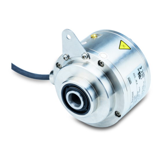
Baumer HUBNER BERLIN HOG 10 Manuel d'installation et d'utilisation
3
Vorbereitung / Preparation
3

Vorbereitung

3.1
Lieferumfang Gerät
6
7
8
5
4
11
Gehäuse Drehgeber HOG 10
1
Gehäuse Fliehkraftschalter FSL
2
Einseitig offene Hohlwelle oder Konuswelle
3
mit Schlüsselfläche SW 13 mm
Spannelement (nur bei einseitig offener Hohlwelle)
4
Stützblech für Drehmomentstütze
5
Sechskantschraube M6x18 mm,
6
ISO 4017, SW 10 mm
Scheibe B6, ISO 7090
7
Selbstsichernde Mutter M6,
8
ISO 10511, SW 10 mm
Rotor FSL
9
Torx-Schraube M4x12 mm
10
Erdungsband ~230 mm lang
11
Klemmenkasten HOG 10
12
Klemmenkasten FSL
13
Status LED
14
2) oder 3)
Option: Heizungsanschluss, siehe Abschnitt 6.1.6.
15
Option M (redundant)
1)
Option mit EMS
2)
Option M (redundant) + EMS
3)
5
1)
2)
2) 3)
12
14
14
1
15
, siehe Abschnitt 6.1.5.
3

Preparation

3.1

Scope of delivery of the device

2
13
12
Housing encoder HOG 10
1
Housing centrifugal switch FSL
2
Blind hollow shaft or cone shaft
3
with spanner flat 13 mm a/f
Clamping element (only for blind hollow shaft)
4
Support plate for torque arm
5
Hexagon screw M6x18 mm,
6
ISO 4017, 10 mm a/f
Washer B6, ISO 7090
7
Self-locking nut M6,
8
ISO 10511, 10 mm a/f
Rotor FSL
9
Screw with torx drive M4x12 mm
10
Earthing strap, length ~230 mm
11
Terminal box HOG 10
12
Terminal box FSL
13
Status LED
14
Option: Heat connection, see section 6.1.6.
15
Option M (redundant)
1)
Option with EMS
2)
Option M (redundant) + EMS
3)
Baumer_HOG10-FSL-T2_II_DE-EN (16A2)
9
3
, see section 6.1.5.
2) or 3)
MB071.1T2 - 11069399
10
2