Baumer HUBNER BERLIN HOG 10 Instructions de montage et d'utilisation - Page 28

Parcourez en ligne ou téléchargez le pdf Instructions de montage et d'utilisation pour {nom_de_la_catégorie} Baumer HUBNER BERLIN HOG 10. Baumer HUBNER BERLIN HOG 10 36 pages. Incremental encoder with connecting cable ölfle
Également pour Baumer HUBNER BERLIN HOG 10 : Manuel d'installation et d'utilisation (36 pages), Manuel d'installation et d'utilisation (40 pages), Instructions de montage et d'utilisation (40 pages), Manuel d'installation et d'utilisation (40 pages), Instructions de montage et d'utilisation (40 pages), Instructions de montage et d'utilisation (40 pages), Instructions de montage et d'utilisation (32 pages), Instructions de montage et d'utilisation (36 pages), Instructions de montage et d'utilisation (28 pages)
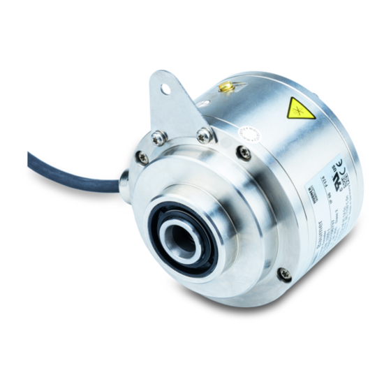
Baumer HUBNER BERLIN HOG 10 Instructions de montage et d'utilisation
7
Elektrischer Anschluss / Electrical connection
7.4

Belegung Anschlusskontakte

K1
K1
K2
K2
+UB
Betriebsspannung nicht auf Ausgänge
legen! Zerstörungsgefahr!
Spannungsabfälle in langen Leitungen
berücksichtigen (Ein- und Ausgänge).
7.5
Sensorkabel HEK 8 (Zubehör)
Es wird empfohlen, das Baumer Hübner
Sensorkabel HEK 8 zu verwenden oder
ersatzweise ein geschirmtes, paarig ver-
seiltes Kabel. Das Kabel sollte in einem
Stück und getrennt von Stromkabeln
verlegt werden.
Kabelabschluss:
HTL: 1...3 kΩ
TTL: 120 Ω
Rot/Red = +UB
Blau/Blue =
Weiß/White = K1
Braun/Brown = K1
Grün/Green = K2
Gelb/Yellow = K2
Grau/Grey = K0
Rosa/Pink = K0
Schwarz/Black = ---
Violett/Violet = ---
25
K0
K0
Baumer_HOG10-HOG10G-Harting_T1_DE_EN_202011_MI_11145664 (20A2)
7.4

Connecting contacts assignment

Ansicht X
Anschlusskontakte,
siehe Abschnitt 7.1.1.
View X
Connecting contacts,
see section 7.1.1.
Do not connect voltage supply to
outputs! Danger of damage!
Please, beware of possible voltage drop
in long cable leads (inputs and outputs).
7.5

Sensor cable HEK 8 (accessory)

Baumer Hübner sensor cable HEK 8 is
recommended. As a substitute a shielded
twisted pair cable should be used.
Continuous wiring without any splices or
couplings should be used. Separate signal
cables from power cables.
Cable terminating resistance:
HTL: 1...3 kΩ
TTL: 120 Ω
Aderendhülsen benutzen.
Use core-end ferrules.
Kabelschirm
Cable shield
MB136T1 - 11145664