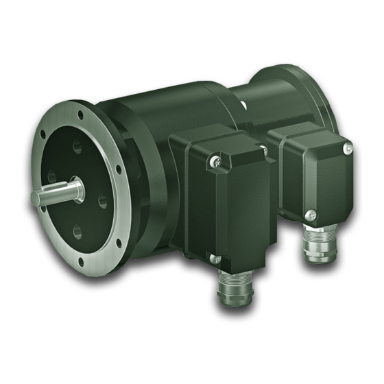
Baumer HUBNER BERLIN SAFETY POG 90 + ESL 90 Instructions de montage et d'utilisation - Page 22
Parcourez en ligne ou téléchargez le pdf Instructions de montage et d'utilisation pour {nom_de_la_catégorie} Baumer HUBNER BERLIN SAFETY POG 90 + ESL 90. Baumer HUBNER BERLIN SAFETY POG 90 + ESL 90 32 pages. Incremental encoder with integrated electronic speed switch
Également pour Baumer HUBNER BERLIN SAFETY POG 90 + ESL 90 : Instructions de montage et d'utilisation (32 pages)

6
Elektrischer Anschluss / Electrical connection
6.2
ESL
6.2.3
ESL 93
(3 Relais-Treiber, 3 Schaltdrehzahlen)
6.2.3.1
Anschlussbelegung
Ansicht Y
Anschlussklemmen,
siehe Abschnitt 6.2.1.2.
View Y
Connecting terminal,
see section 6.2.1.2.
6.2.3.2
Blockschaltbild
G
3~
ESL 93
6.2.3.3
Empfohlene Ausgangsbeschaltung
6.2.3.4
Ausgangsschaltverhalten
12 VDC
out 1/2/3
-n
n = Drehzahl / Speed
ns = Eingestellte Schaltdrehzahl / Adjusted switching speed
19
n
1
n
2
n
3
R
/R
/R
1
2
3
ES 93
0 V
0 V
-ns (1,2,3)
Baumer_POG90-ESL_DE_EN_202210_MI_11067531 (22A1)
6.2
ESL
6.2.3
ESL 93
(3 relay driver, 3 switching speeds)
6.2.3.1
Terminal assignment
Kabel:
5-adrig abgeschirmt,
Länge: ≤200 m bei
1 mm
2
Cable:
5 leads shielded,
length: ≤200 m at
1 mm
2
6.2.3.2
Block circuit diagram
COMP
COMP
COMP
6.2.3.3
Recommended output circuit
470
12 VDC
6.2.3.4
Switching characteristics
0
+ns (1,2,3)
Querschnitt
cross-section
U
= 12 VDC
R
0 V (GND)
R
1
0 V
R
2
0 V
R
3
0 V
out 1/2/3
+n
MB154.2 - 11067531
