Baumer Hubner POG 10 + FSL Instructions de montage et d'utilisation - Page 10
Parcourez en ligne ou téléchargez le pdf Instructions de montage et d'utilisation pour {nom_de_la_catégorie} Baumer Hubner POG 10 + FSL. Baumer Hubner POG 10 + FSL 32 pages. Incremental encoder with integrated centrifugal switch
Également pour Baumer Hubner POG 10 + FSL : Instructions de montage et d'utilisation (36 pages)
4
Montage / Mounting
4
Montage
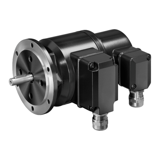
In den Bildern am Beispiel des POG 10 +
FSL Standard. Gleiche Montageschritte
bei allen anderen Versionen.
4.1
Schritt 1
Anzugsmoment:
Tightening torque:
M
= 1 Nm
t
*
19
4.2
Schritt 2
* Siehe Seite 6
See page 6
Antriebswelle einfetten.
Die Antriebswelle sollte einen
möglichst kleinen Rundlauffehler
aufweisen, da dieser zu einem
Winkelfehler führen kann. Rundlauf-
fehler verursachen Vibrationen, die die
Lebensdauer des Gerätes verkürzen
können.
7
2.5 mm
4
Mounting
Pictures showing type standard
POG 10 + FSL as example. Same mount-
ing steps for all versions.
4.1
Step 1
4.2
Step 2
*
*
17
18
Lubricate drive shaft.
The drive shaft should have as less
runout as possible because this can
otherwise result in an angle error.
Runouts can cause vibrations, which
can shorten the service life of the
device.
Baumer_POG10-FSL-T1_II_DE-EN (20A1)
10 mm
MB069.1T1 - 11055670