Baumer X 700 Manuel - Page 40
Parcourez en ligne ou téléchargez le pdf Manuel pour {nom_de_la_catégorie} Baumer X 700. Baumer X 700 41 pages. Absolute encoder profibus-dpv0 (with bus cover and ssi coupler)
Également pour Baumer X 700 : Manuel (26 pages)
6. Connection Assignment and Commissioning
6.1. Mechanical attachment
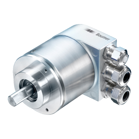
Shaft encoder
• Mount the encoder housing on the flange mounting holes with three screws (square flange with 4 screws).
Observe the thread diameter and thread depth.
• As an alternative the encoder can be mounted in any angled position with eccentric mountings, see
Accessories.
• Connect the drive shaft and encoder shaft via a suitable coupling. The shaft ends may not touch each
other. The coupling must compensate shifting caused by temperature and mechanical play. Observe the
permissible axial or radial axis load. For suitable connections, see Accessories.
• Firmly tighten the mounting screws.
6.2. Electrical connection
6.2.1. Description of connections
Pin
Assignment
CAN_L
CAN Bus Signal (dominant Low)
CAN_H
CAN Bus Signal (dominant High)
UB
Supply voltage 10 - 30 VDC
GND B
Ground connection for UB
CAN_GND
Optional GND reference for CAN interface
6.2.2. Connection assignment of M12 plug
Pin
Assignment
1
GND B
2
UB
3
CAN_GND
4
CAN_H
5
CAN_L
3
4
5
2
1
Manual_GXP5_417_Lift_EN.doc
04.05.11
40/41
Baumer IVO GmbH & Co. KG
Villingen-Schwenningen, Germany