Baumer HUBNER TDP 0,2 Series Instructions de montage et d'utilisation - Page 31

Parcourez en ligne ou téléchargez le pdf Instructions de montage et d'utilisation pour {nom_de_la_catégorie} Baumer HUBNER TDP 0,2 Series. Baumer HUBNER TDP 0,2 Series 32 pages. Tachogenerator (doppel-tachogenerator), tachogenerator (twin tachogenerator)
Également pour Baumer HUBNER TDP 0,2 Series : Manuel d'installation et d'utilisation (32 pages), Manuel d'installation et d'utilisation (32 pages), Manuel d'installation et d'utilisation (28 pages), Instructions de montage et d'utilisation (28 pages), Instructions de montage et d'utilisation (32 pages), Instructions de montage et d'utilisation (32 pages), Instructions de montage et d'utilisation (28 pages)
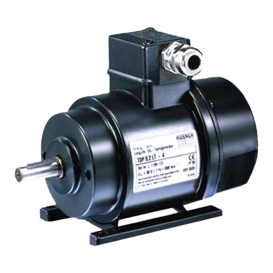
Baumer HUBNER TDP 0,2 Series Instructions de montage et d'utilisation
• Operating temperature:
• Resistance:
• Connection:
TDP 0,2 + ESL 90, TDP 0,2 + ESL 93
• Rotor moment of inertia:
• Weight approx.:
TDPZ 0,2 + ESL 90, TDPZ 0,2 + ESL 93
• Rotor moment of inertia:
• Weight approx.:
10.4

Type data

voltage
Type
[mV/rpm]
TDP0,2LT(LS)-6
TDP0,2LT(LS)-7
TDP0,2LT(LS)-10
TDP0,2LT(LS)-5
TDP0,2LT(LS)-4
TDP0,2LT(LS)-3
TDP0,2LT(LS)-1
TDPZ0,2LT-7
TDPZ0,2LT-10
TDPZ0,2LT-5
TDPZ0,2LT-4
TDPZ0,2LT-3
Superimposed ripple (for τ
10.5

Replacement switching diagram

Polarity for positive direction of rotation, see section 5:
TDP:
TDP:
1A1/2A1: +
R
L
A
A
U
(n)
0
Tachogenerator
τ
≈ R · C
τ
RC
A
MB079.2 - 11115290
Open-
Minimum load required
circuit
depending on speed range
(DC)
0 - 3000:
U
R
0
L
[kΩ]
10
≥0.1
20
≥0.3
30
≥0.7
40
≥1.2
60
≥2.7
100
≥7.5
150
≥16
Twin tachogenerator with two separate tachogenerator voltages
(The data refer to each of the two tachogenerator outputs)
20
≥1.2
30
≥2.7
40
≥4.8
60
≥11
100
≥30
= 0.7 ms):
≤0.5% peak-peak
RC
A1: +
A2: -
1A2/2A2: -
R
A1
U(n)
R
L
A2
L
A
R
L
Baumer_TDP02-ESL-TDPZ02-ESL_II_DE-EN (20A1)
-20...+85 °C
IEC 60068-2-6:2007: Vibration 5 g, 10-2000 Hz
IEC 60068-2-27:2008: Shock 150 g, 1 ms
2x terminal box
1.4 kgcm
2
3.2 kg
1.5 kgcm
2
3.4 kg
[rpm]
0 - 6000:
0 - n
R
R
L
L
[kΩ]
[kΩ]
≥0.3
≥0.9
≥1.2
≥3.3
≥2.7
≥7.5
≥5
≥13.5
≥11
≥30
≥30
≥30
---
≥30
≥4.8
≥14
≥11
≥30
≥20
≥54
≥44
≥120
≥120
---
≤0.2% rms
(VDE)
(VDE)
C
U(n) = U
(n)
0
Maximum
Armature
operating
resistance
speed
:
max
n
R
max
A
[rpm]
10000
10000
10000
10000
10000
6000
4000
10000
10000
10000
10000
6000
U(n)
-n
-U(n)
R
L
≈ U
(n) for R > R
R
+ R
0
A
L
10
Armature
inductance
(20 °C)
L
A
[Ω]
[mH]
3
6
11
23
26
50
47
90
99
200
271
550
630
1260
19
45
42
103
70
170
160
390
445
1080
U
(n) ≈ U(n)
0
n
>> R
L
A
28