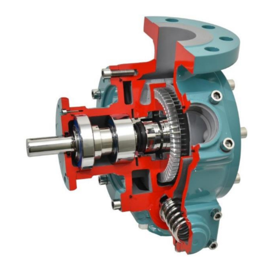
Dover Ebsray R75 Manuel d'installation, d'utilisation et d'entretien - Page 7
Parcourez en ligne ou téléchargez le pdf Manuel d'installation, d'utilisation et d'entretien pour {nom_de_la_catégorie} Dover Ebsray R75. Dover Ebsray R75 12 pages. Regenerative turbine pump

5.5 IMPELLER & MECHANICAL SEAL REPLACEMENT
The removal or replacement of the Impeller (3) or Mechanical
Seal Assembly (56) requires the respective Kits K900300 and
L752-27-096-05 supplied by Ebsray.
Impeller Kit:
Impeller (3)
Impeller Key (8)
M8x12mm socket
Cover O-ring (4)
2 0.004 inch (0.1mm)
feeler gauges
2 M8x75mm setscrews
The pump should rest on its inlet flange.
Remove the Cover's eight cap head setscrews (6). If
1.
required fit two of the setscrews to the tapped jacking
holes.
2.
Remove the Cover (2), remove the Cover O-ring (4),
discard and replace with lightly lubricated new O-ring.
The cover is a very neat fit into the pump body. Do not use
excessive force to remove the cover. If the cover gets stuck,
gently rock loose or gently tap loose with a soft mallet.
Loosen the Impeller's locking screw (10) and remove the
3.
Impeller (2) and Impeller Key (8). If required, use the
provided M8x75mm setscrews as jacking screws.
4.
Remove the Circlip (58). At this point you can remove the
dynamic element by using two of the four cartridge cap
head setscrews (57A) and fit them to the back of the Seal
Sleeve (42) (part of the dynamic element (56)) and use
as extraction screws. If replacing the entire seal follow
steps below.
5.
Remove the cartridge cap head setscrews and screw two
of them into the Mechanical Seal Cartridge's (57) tapped
jacking holes. Jack the Cartridge and/or Mechanical Seal
Assembly (56) off the shaft.
6.
Remove the dynamic element (41, 42, 45, 46
assembled) and Seal Seat (40) from the Cartridge.
Remove the O-rings (57B & C) from the Cartridge and
discard.
7.
Fit a small screwdriver or punch to
the Cartridge's holes and gently tap
the Lip Seal (55) out (See Figure 4).
8.
Clean the Cartridge using non-
residual contact cleaner or similar.
9.
Loosely fit the new Lip Seal to the
Cartridge (with the lip facing out,
See Figure 5). Using the piece of 1-
1/4 inch pipe as a drift, gently tap the
Lip Seal into the Cartridge. Ensure
that the Lip Seal is flat (flush) by
checking the holes in the back of the
Cartridge.
10.
Fit the smallest new O-ring (48) to
the Seal Seat and lightly lubricate.
11.
Without removing the protective cover, press the Seal
Seat into the Cartridge with fingers (ensuring complete
and square engagement).
12.
Remove the protective cover from the Seal Seat, clean
with non-residue contact cleaner.
Mechanical Seal Kit:
Seal Seat O-ring (48)
Cartridge O-ring (57B)
Cartridge O-ring (57C)
Oil Seal – Secondary (55)
Mechanical Seal Assembly
(56)
NOTE:
Figure 4
Figure 5
13.
Fit the new O-rings (57B & 57C) to the Cartridge and
lightly lubricate. The smaller cross section O-ring goes
on the back.
14.
Lightly lubricate the Cartridge O-rings, Lip Seal and bore
of the Bearing Housing (20).
15.
Aligning the four holes of the Cartridge with the tapped
holes in Bearing Housing, fit the Cartridge to the
Bearing Housing.
Fit the four Cartridge cap head setscrews with 'Loctite
16.
243' or similar and tighten to 7N-m (5ft-lbs).
17.
Remove the protective cover from the dynamic
element and clean face with non-residual contact
cleaner. Lightly lubricate the new internal Shaft O-ring
(46) and lubricate seal face with clean light machine
oil.
18.
Aligning the dynamic element pin
with the Impeller's keyway, fit the
dynamic element onto the shaft
and rest gently on the Seal Seat's
face.
19.
Loosely fit the Circlip (58) onto the
shaft. Using the 1-1/4 inch pipe as a
press tool, snap the circlip into
place. Ensure the Circlip is correctly
seated (See Figure 6).
20.
Rotate the Shaft (21) such that the
impeller keyway is at the 3 o'clock
position. Fit the new Impeller Key (8) to the keyway.
21.
To set the Impeller (3)
clearance, tape the
feeler
gauges
shown in Figure 7
such that the ends
come up against the
shaft.
22.
Fit the Impeller to the
shaft and then fit the
Impeller's
locking
screw (10) tightly to
the
Impeller
Loctite 243 or equal.
The feeler gauges must be aligned horizontally at 9 o'clock &
3 o'clock. While applying even pressure to the Impeller,
tighten the locking screw.
23.
Remove the feeler gauges. If they are tight or stuck
gently tap the shaft on the opposite side while pulling
the feeler gauges.
24.
Gently fit the Cover (2) to the Body (1).
Do not force the cover into the body.
If it gets stuck, gently rock loose or
gently tap it in with a soft mallet.
25.
Do a final check to ensure the Cover
O-ring (4) is correctly located (See
Figure 8), then hand fit the eight cover
cap head setscrews (6). Torque
setscrews to 100Nm (75 ft-lb's)
7
Publication No.: 2750-17
Figure 6
as
9 O'CLOCK
3 O'CLOCK
POSITION
POSITION
with
Figure 7
NOTE:
KEYWAY
Figure 8
