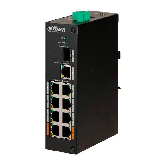
Dahua DH-PFS3211-8GT-120 Manuel de démarrage rapide - Page 13
Parcourez en ligne ou téléchargez le pdf Manuel de démarrage rapide pour {nom_de_la_catégorie} Dahua DH-PFS3211-8GT-120. Dahua DH-PFS3211-8GT-120 17 pages. 4/8-port unmanaged hardened switch

No.
1
2
3
Step 1
Connect the device to the ground.
Step 2
Take off the power terminal plug from the device.
Step 3
Insert one end of the power cable into the power terminal plug according to requirements.
The sectional area of the power cable must be more than 0.75 mm
area is 2.5 mm
Step 4
Insert the plug that is connected to the power cable back into the corresponding power
terminal socket of the device.
Step 5
Connect the other end of the power cable to the corresponding external power supply
system according to the power supply requirements marked on the device, and check the
power indicator of the device. If the indicator is on, then the power connection is correct.
4.3 Connecting SFP Ethernet Port
We recommend wearing antistatic gloves before installing the SFP module, and wearing an
antistatic wrist, and confirm that the antistatic wrist is securely linked to the surface of the gloves.
Step 1
Lift the handle of SFP module vertically upward and attach it to the top hook.
Step 2
Hold the SFP module on both sides and push it gently into the SFP slot untill the SFP
module is firmly connected to the slot (You will feel that both the top and bottom spring
strip of the SFP module are securely attached with the SFP slot).
The device uses laser to transmit signals via optical fiber cables. The laser conforms to the
requirements of level 1 laser products. To avoid injury to your eyes, do not look at the 1000
Base-X optical port directly when the device is powered on.
● When installing the SFP optical module, do not touch the gold finger of the SFP optical
module.
● Do not remove the dust plug of the SFP optical module before connecting the optical
port.
● Do not directly insert the SFP optical module with the optical fiber inserted into the slot.
Unplug the optical fiber before installing it.
Table 4-1 Power terminal description
Name
DIN rail port (–).
DIN rail port (+).
Power adapter port.
2
).
7
2
(maximum sectional
