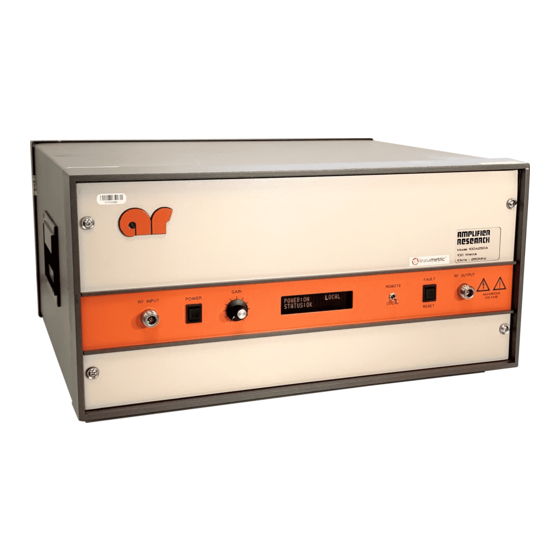
Amplifier Research 100A250A Manuel - Page 7
Parcourez en ligne ou téléchargez le pdf Manuel pour {nom_de_la_catégorie} Amplifier Research 100A250A. Amplifier Research 100A250A 19 pages.

Model 100A250A
2.2.2.2
Selecting Remote Operation
The Model 100A250A can be placed in the remote operation mode at any time by
switching the FUNCTION switch on the front panel to the REMOTE position. In this
mode, control is transferred to the selected remote interface and all front panel controls are
inoperative with the exception of the FUNCTION switch. The amplifier's initial state
will be Power Off. The front panel VFD will indicate REMOTE until the unit is returned
to the local operation mode.
2.2.2.3
Interface Selection
The Model 100A250A can be controlled via either the IEEE-488 or RS-232 interface; which
interface is active is determined by the position of Switch 6 of the rear panel Dual In-Line Package
(DIP) switch located between the two interface connectors. If Switch 6 is in the "on" (1) position,
the RS-232 interface will be active; if Switch 6 is in the "off" (0) position, the IEEE-488 interface
will be active.
2.2.2.4
Interface Set-up
Switches 1–5 of the rear panel DIP switch are used to select either the RS-232 communication
(BAUD) rate or the IEEE-488 device address, depending upon which interface is active. (Note:
These switches are only read at device power-up. In order for changes made in these switch
settings to take place, AC power must be removed and then re-applied to the Model 100A250A.)
2.2.2.4.1 RS-232 BAUD rate selection
The serial communication (BAUD) rate can be set to five different levels. Selections are made by
the positions of Switches 1–5 of the rear panel DIP switch. The following is a list of the available
BAUD rates and the corresponding DIP switch positions:
BAUD Rate
1200
2400
9600
19,600
76,800
(Note: Any other combination of switch settings will result in a BAUD rate equal to 1200.)
2.2.2.4.2 IEEE-488 device address selection
The IEEE-488 device address can be set to any number between 1 and 30. This selection is made
by setting Switches 1–5 of the rear panel DIP switch to the binary equivalent of the number.
Table 2-1 illustrates this switch selection.
Switch On (1)
1 only
2 only
3 only
4 only
5 only
Manual Text
2-3
REV -
