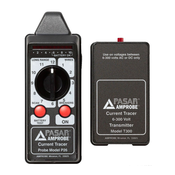
Amprobe CT-326-C Manuel de l'utilisateur - Page 13
Parcourez en ligne ou téléchargez le pdf Manuel de l'utilisateur pour {nom_de_la_catégorie} Amprobe CT-326-C. Amprobe CT-326-C 20 pages. Current tracer
Également pour Amprobe CT-326-C : Manuel (2 pages)

Wires in Floors, Walls, Ceilings
IMPORTANT: Since the load current on the conductors supplying power to the transmitter flows
in opposite directions on the "hot" and neutral wires, the magnetic field surrounding these
conductors radiates in the opposite direction. (See Fig. 6). Therefore, when the "hot" and
neutral wires are within close proximity, they tend to cancel the force of each other's magnetic
field. For this reason, it is advisable to separate the current paths in order to trace them. The
easiest and most effective way to do this is to use a separate ground, not adjacent to the ground
of the circuit being traced, to provide a current path back to the power source.
1. Plug the pigtail connector into the transmitter
2. Attach one of the pigtail connector's insulated clip leads to a separate ground, such as a
water pipe (see Fig. 5). As an alternative, use the neutral wire from another circuit away from
the circuit being traced.
3. Attach the other lead to the "hot" conductor of the circuit you wish to trace. The
transmitter's LED will blink to indicate it is operating and that the circuit is complete.
4. Turn the receiver's range switch to "Scan-8."
5. Press the receiver's "ON" button and wait for it to calibrate.
6. Hold the receiver's tip close to the floor, wall, or ceiling where you suspect the conductor is
located.
7. Sweep the receiver across large areas until the receiver's signal locates the conductor. Narrow
down the location of the conductor by changing the angle of the receiver and adjusting the
range switch as necessary.
Fig.5 Separate ground connection
NOTE: Be sure to follow the "hot"
conductor and not the ground path or
neutral wire used to supply power to the
transmitter.
1.800.561.8187
I
I
Fig.6 Direction of load current on conductors
11
www.
.com
