Amprobe MO-100 Manuel de l'utilisateur - Page 18
Parcourez en ligne ou téléchargez le pdf Manuel de l'utilisateur pour {nom_de_la_catégorie} Amprobe MO-100. Amprobe MO-100 18 pages. Milliohm meter
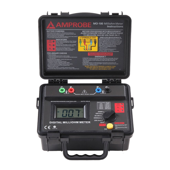
Current Circuit
Fuse(F2)
• Potential Circuit Fuse
Fuse protection is provided on the potential terminals. This fuse is
situated under the Printed Circuit Board. To access it, you need to
unscrew the four mounting screws which are holding the font panel.
Two of these screws are located under the foots, and the two others are
located inside the battery compartment.
The fuse is automatically blow by the crowbar, should voltage be
present on the resistance under test. This is to prevent damage to the
instrument. If the preliminary tests does not lit R P this is indicative of
this fuse being blown. (HBC, 0.5A, 250Vac, Slow Blow)
Potential Circuit
Fuse(F1)
14