Advanced Amplifiers AA-1218G-3.5KW-PT Manuel de l'utilisateur - Page 6
Parcourez en ligne ou téléchargez le pdf Manuel de l'utilisateur pour {nom_de_la_catégorie} Advanced Amplifiers AA-1218G-3.5KW-PT. Advanced Amplifiers AA-1218G-3.5KW-PT 14 pages. R.f. microwave amplifier system

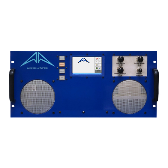
Front Panel Display
Front panel display interface consists of 8 screens, Home, Fault Count, Floating Deck, High Voltage,
Elapsed Time Meters, Temperature, Input Pulses and Settings. A panel of 8 buttons on the left side
allows to switch between screens. There is also a status area in the lower right corner which constantly
shows the current state of the unit.
There are 4 main states of operation of the amplifier. In WARM UP, the unit is waiting until the tube
heater achieves the correct temperature and all the currents and voltages stabilize. In this state the status
bar shows how much time is left to finish the warm up. After the warm up time finishes the unit enters
STANDBY. In STANDBY and OPERATE the status area shows ambient temperature inside the unit.
Finally, in the case of RESET, the status area shows how many faults were present at the time RESET
state was triggered.
Picture 3: Home screen, Standby
Picture 4: Home Screen, Reset
Home Screen (picture 3) is the screen shown by default after the unit turns on.
Picture 5: Floating Deck Screen
Picture 6: High Voltage Screen
Floating Deck and High Voltage screens (picture 5 and 6) present readings of the monitored
parameters. The values are updated in real time.
Page 6 of 14
